
Verification
The NPU’s functionalities were verified in Verilog testbenches and
Virtuoso AMS(Analog/Mixed-Signal) simulations. Since NPU has multiple operating
modes, we designed a comprehensive testbench with 5 tests to verify that NPU, in
each of its operating modes, had the exact computation results as our MATLAB
fixed-point model.
The five tests are:
- TEST 1: Verify the manual control and ReLU bypass function
- TEST 2: Verify the comparator function (largest & index)
- TEST 3: Verify the debugging system
- TEST 4: Verify the entire inference process with FSM control and PISO_OUT
- TEST 5: Verify the entire inference process with FSM control and FIFO/Comparator
Verilog Testbench
To ensure that the NPU behavior is a complete match with the MATLAB results, we
exported 10,000 test images, together with all the neurons(hidden layer 1-2, output
layer) from MATLAB to Verilog testbench to verify each neuron calculation was correct.
TEST 1-5 were performed on both the RTL model and synthesized netlist. As their results
resembled, we only described the test results on the RTL model.
In TEST 1, we verify the manual mode of FSM, together with the ReLU bypass function.
The tested path is shown in Figure 1.
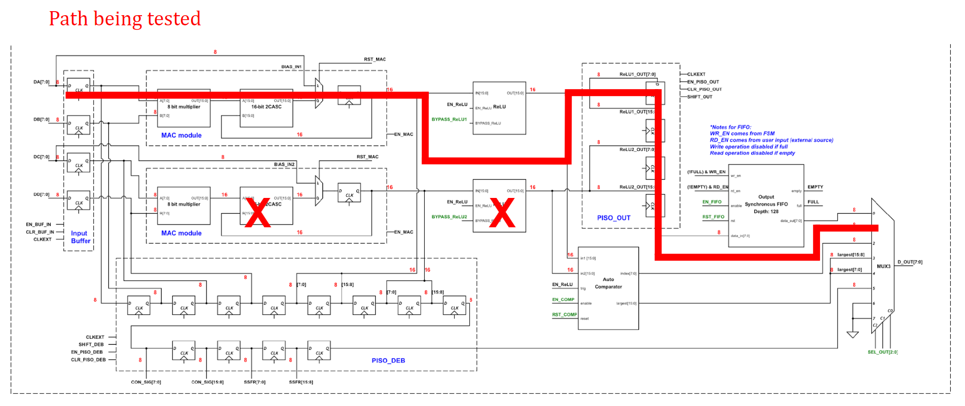
Figure 1: TEST 1 tested path
Figure 2 shows the result of classifying 5 images under manual mode. For each image, each mismatched neuron from any layer would add to its error count, and the sum of error counts across all tested images, which we call the total error count, needs to equal 0 for TEST 1 to pass.
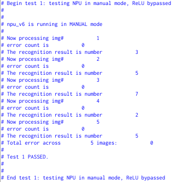
Figure 2. TEST 1 results, 5 images
In TEST 2, we verify whether the comparator gives us the correct “index” and “largest.” Since the comparator would be heavily utilized in TEST 5, we only tested whether it outputs the correct index and largest value for 1 image. The tested path is shown in Figure 3, and the results are shown in Figure 4.
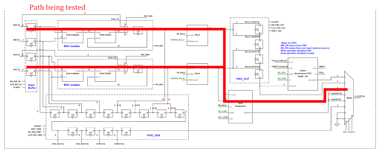
Figure 3. TEST 2 tested path
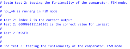
Figure 4. TEST 2 results, 1 image
In TEST 3, we test NPU’s debugging system, i.e. the functionality of the debugging PISO, to see whether it outputs the correct values in sequence, and whether the NPU successfully generates correct prediction for the image after the debugging ends. The tested path is shown in Figure 5, and the results are shown in Figure 6. Note that NPU can resume working on the image after it exits debugging mode.
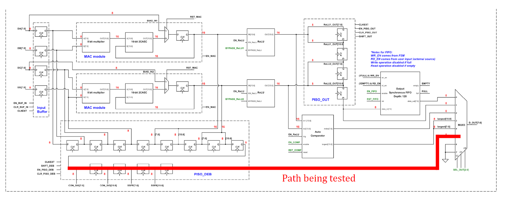
Figure 5. TEST 3 tested path
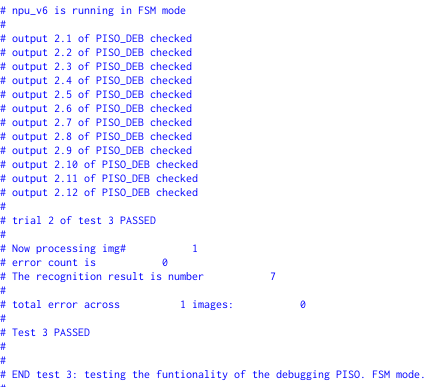
Figure 6. TEST 3 results
In TEST 4, we verify the entire inference process with FSM and PISO_OUT. Similar to TEST 1, for each image, each neuron value is compared with expected value, and TEST 4 passes only if the total error count is 0. The tested path is shown in Figure 7 and the test results of inferring 50 images are shown in Figure 8.
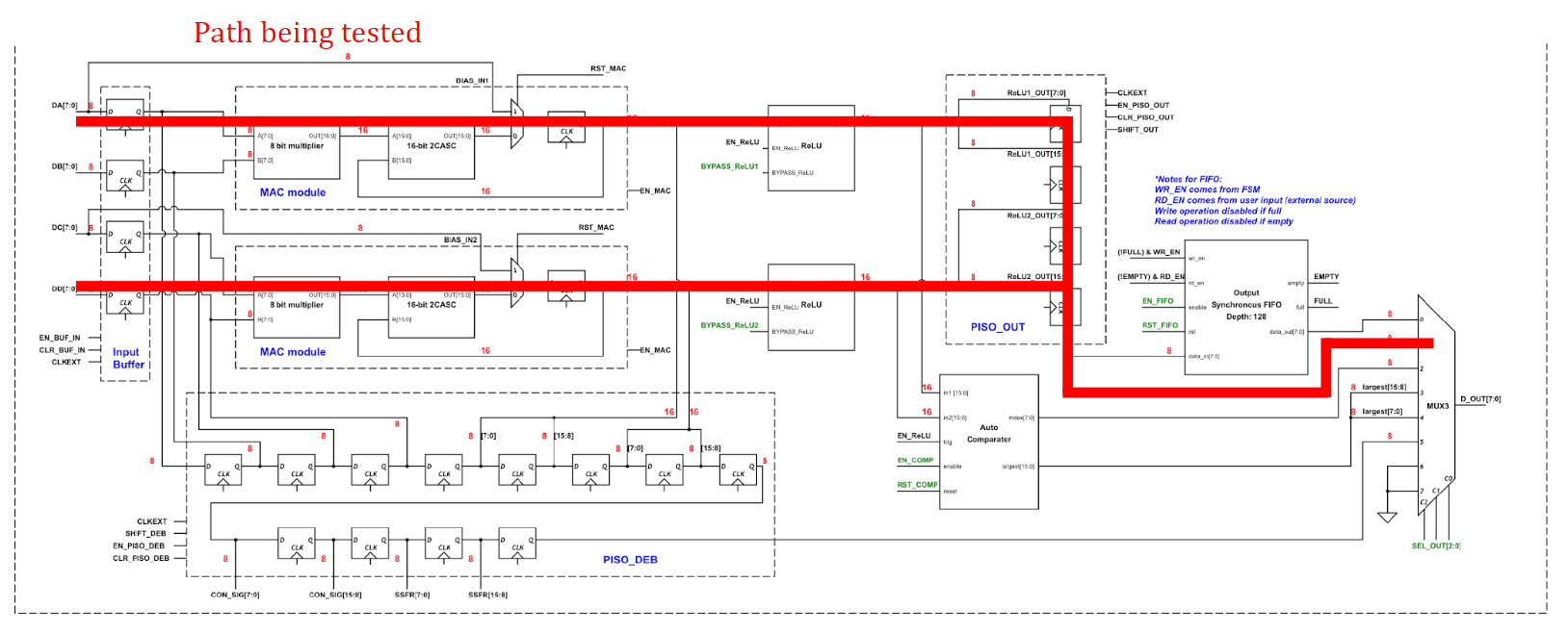
Figure 7. TEST 4 tested path
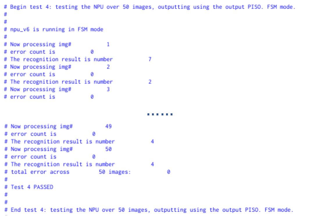
Figure 8. TEST 4 results, 50 images
In TEST 5, we verify the entire inference process with FSM, FIFO and Comparator, which is our desired operating mode. As seen in Figure 9, for the two hidden layers, neurons are stored in the FIFO so that they can be accessed when needed(red path), compared to the PISO option which is going to stream out the neurons whenever they are ready. In the output layer, neurons are instead fed into the comparator, which will directly output the prediction once it receives all the neurons(blue path). Figure 10 shows the result of TEST 5 over 50 images. For each image, each neuron and the final recognition result are compared with the expected results.
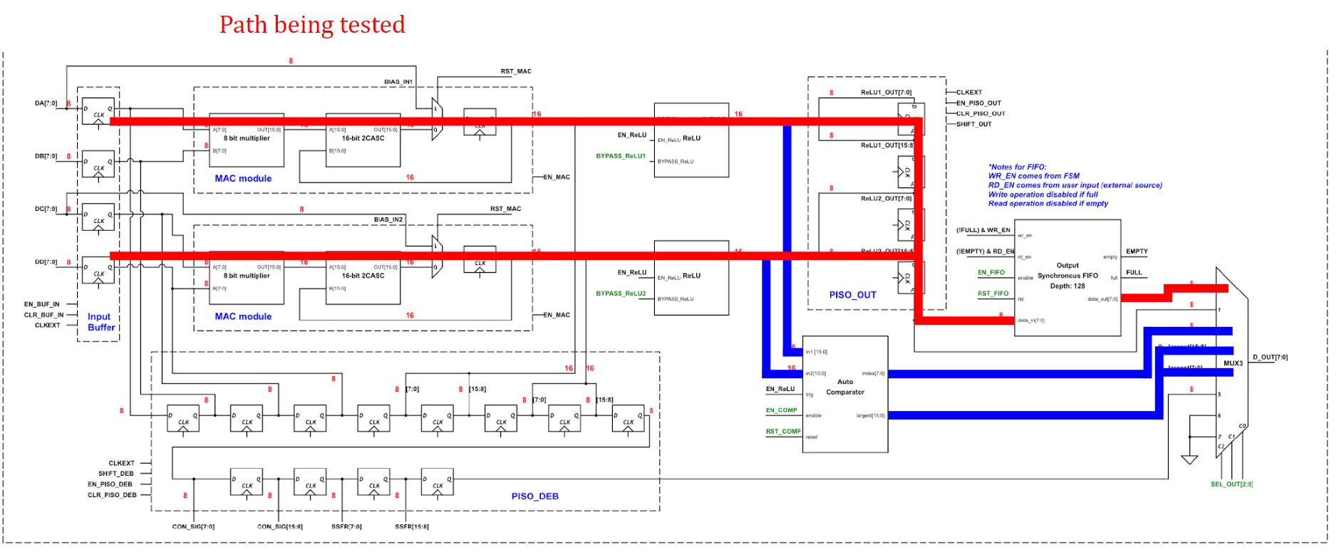
Figure 9. TEST 5 tested path. Hidden layer 1-2 follow red path, final layer follows blue path
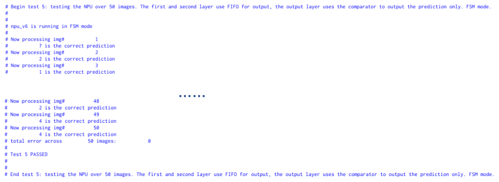
Figure 10. TEST 5 results, 50 images
AMS simulation
After place and route, verification became much more difficult. As a digital project, one could not imagine programming each input signal as a Virtuoso’s piecewise linear voltage source. This was when AMS simulation became handy. We were able to transform the Verilog testbench as a Verilog checker, connected to the NPU core as an instance in Virtuoso, as shown in Figure 11. This approach relies on the Verilog checker to serve as the host of the NPU, and is essentially similar to the approach of Demo 2: FPGA+NPU , where we reprogrammed the testbench in synthesizable Verilog code and have the FPGA serve as the host.
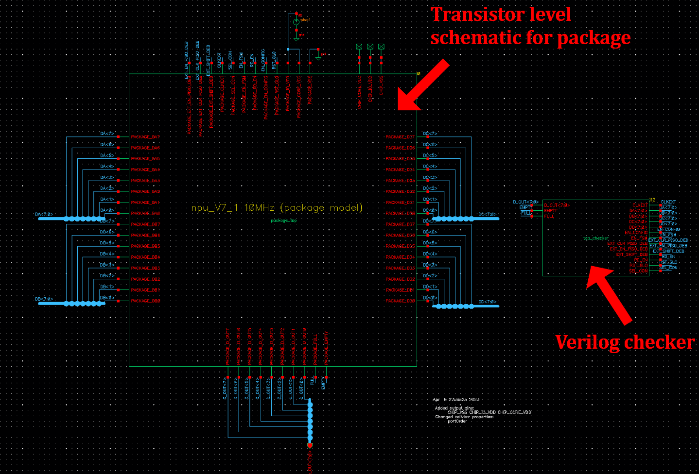
Figure 11. NPU package model and Verilog checker in Virtuoso
In Virtuoso’s hierarchy editor, we can easily switch between different “view” options
of the NPU core, i.e. layout, PEX.
We ran the five tests with AMS simulation, and they all passed. Note that AMS simulation
takes forever to run. Some take hours to run, and some take days or weeks. Figure 12
and 13 show the waveforms of running TEST 5 on one image. Since TEST 5 uses comparator
for output, we could interpret the results from the waveform.
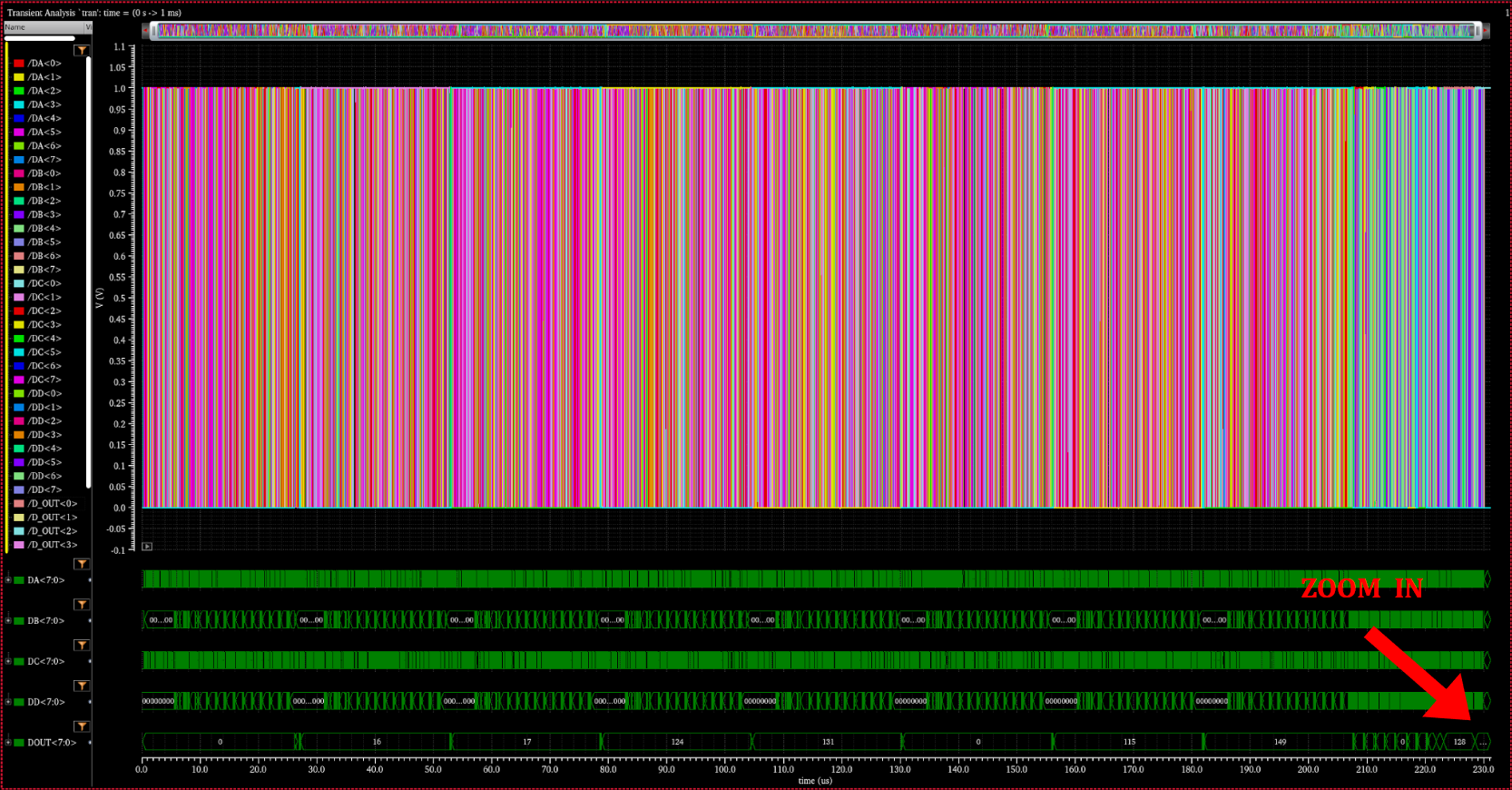
Figure 12. AMS simulation TEST 5 waveform
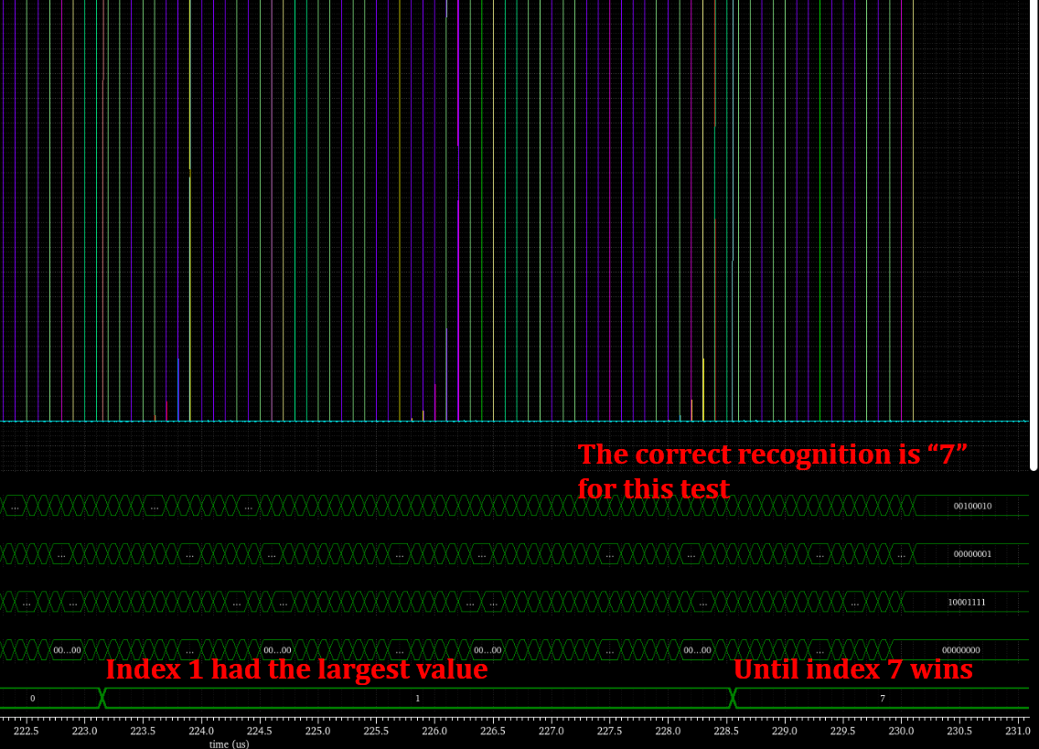
Figure 13. Zoomed in version of Figure 12.
Comment: Verilog is very bad with its string operations, so it took us a while to figure out how to access the numerous input files throughout different runsets. Verilog also doesn’t support arrays as ports, leading to a series of packing and unpacking. SystemVerilog could be a better choice for this specific project.