
System Overview
Project Goal & Background:
We started the entire project at a very high level, that is, we want to design a system that can accept an image including a single hand-written number and recognize the number in the system. This is actually a "vanilla" verision of AIML(Artificial Intelligence & Machine Learning) task, since there are infinite possible ways for people to write a number. Traditional logical programming won't be able to address this task with a high accuracy.
In AIML, the most common method to solve this is using a Neural Network (NN), which in brief, can be interpreted as a representation of certain relations between some inputs and some outputs. The magic of NN is that it can be used to represent any relation, no matter how abstract that is (complexity will be another topic). [4-6] Specifically for our task, the relation should be mapping an image (a bunch of pixels) to an integer number (recognition result). To human, this mapping is fairly easy because we use the pattern+experience to judge the content in the image, rather than deriving the number based on pixels. For example, whenever you see a circle-like shape, you suspect it is a "zero", or if you see two circles on a stack, you suspect that is a "eight". The fact that the circle is close to an ellipse or even a triangle won't affect you judgement. This is however, not easy for computers, since explicitly describing all patterns of numbers and making sure these apply to all types of handwriting is not a trivial task. NN is a proven method to establish this type of abstract mapping relation.
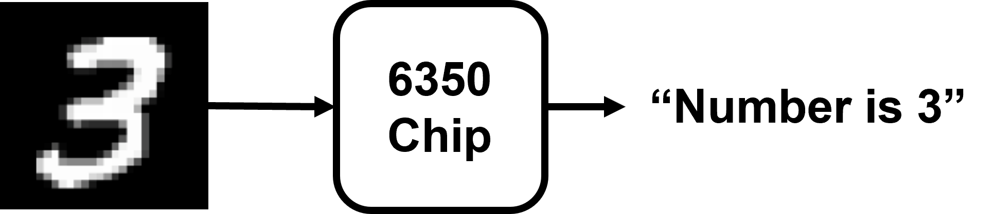
Figure 1. Block diagram for project target
With this in mind, we proposed our NN structure for this task, as shown in the Figure 2. This is a typical perceptron structure with one input layer, one output layer and two hidden layers. The input layer has 256 neurons, both hidden layers have 16 neurons and the output layer has 10 neurons. Assuming the input image is 16 by 16, each pixel can be mapped to one input neuron, thus the NN can accept the information from the entire image. Since there are totally 10 possible outcomes (0~9), each output neuron represents one of the possibilities, and the neuron value represents the probability of this certain outcome. In this way, we successfully established the relation between the input image (256 pixels->256 neurons) and the recognition outcomes (probability of each outcome). The most simple logic is to use the outcome with the highest probability as the recognition results. The reason why this relation can be reliably represented by a NN is not described here. There is a considerable amount of math behind this theory, there is abundant resouce online to explain this.
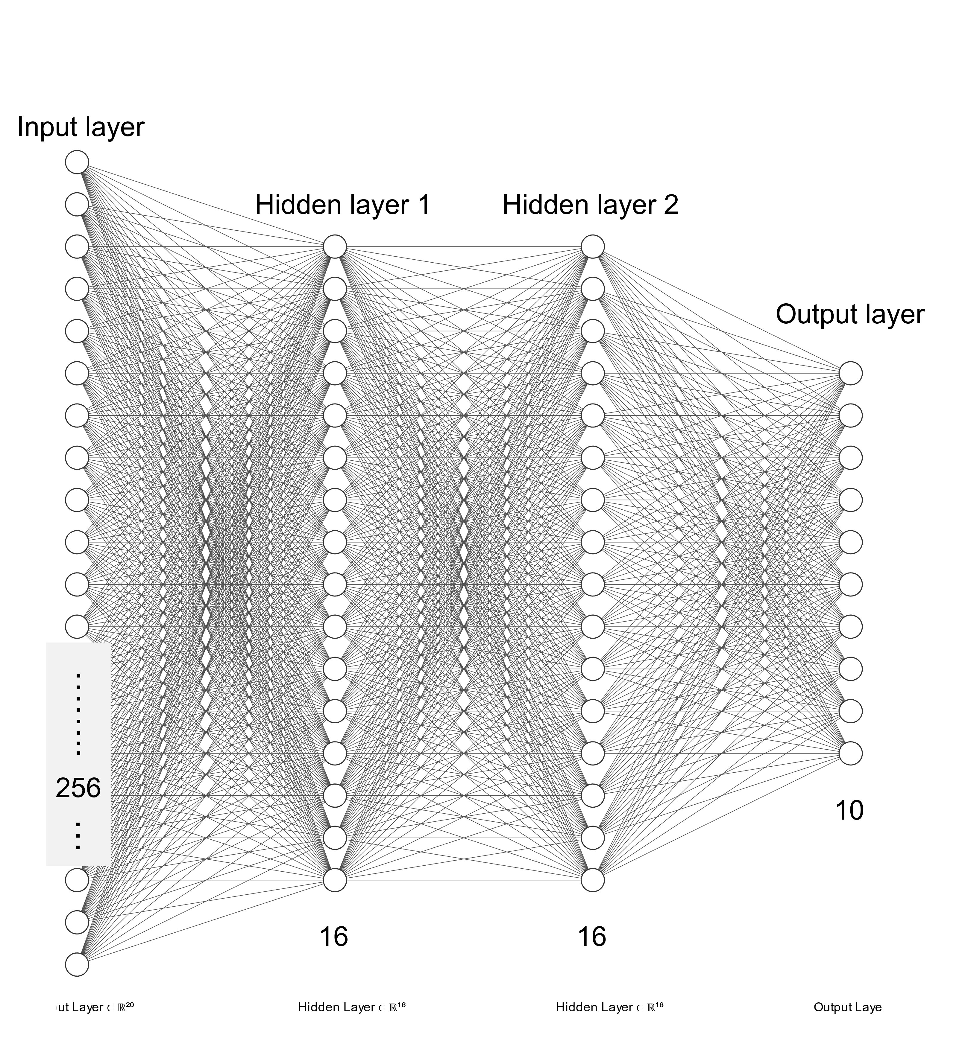
Figure 2. Proposed neural network structure
The connections between neruons in Figure 2 are mathematically described by weights and biases. These are numerical values that determine how the signal will propagate from input to output, i.e. how the inputs will be executed by the NN. The process for obtaining these values is called training, while the process for executing the NN from input to output when given a certain input is called inference. We only focused on the inference process in this project. Mathematically, the inference process can be broken apart into a series of MAC (Multiply and Accumulate) operations that are very close to the dot product of two vectors. For example vector_a = [w1,w2,w3] and vector_b=[x1,x2,x3], the MAC result (also the dot product) of these two vectors is w1*x1+w2*x2+w3*x3. Usually to add additional degees of freedom to the calculation, a bias term and an activation function will be included to the equation. The calculation process of each neruon in our network can be summarized using the equation below:

Figure 3. Using matrix multiplication to represent a series of MAC
where w means the weight, x means the neuron value, ReLU is the activation function we chose for our network. ReLU essentially is finding the maximum number between input and zero.
NPU & Hardware Accelerator:
Until now, the entire task is abstracted from a system-level image recognition task, to a series of MAC operations. A set of MAC operations can be concisely expressed as a matrix multiplication process. For example, if vector_a=[w11,w12,w13], vector_b=[w21,w22,w23], vector_c=[x11,x12,x13], vector_d=[x21,x22,x23], then v_a*v_c, v_a*v_d, v_b*v_c, v_b*v_d can be expressed as the following equation:

Figure 4. Neuron Equation
The problem is further abstracted as a matrix multiplication process, hence essentially we need to design some hardware that can efficiently execute the matrix multiplication, plus additional NN-specific operations such as ReLU. This actually agrees with the typical concept of hardware accelerator, where dedicated hardware is designed to boost the execution performance of certain operations, in this case the matrix multiplication process. NN is just an additional layer of wrapper on top of matrix multiplication, thus the hardware we are designing here is also called Neural Processing Unit (NPU).
System-level Block Diagram
With all the background information above, originally we wanted to design a standalone system, which can accept one image from external input and then do the computation entirely on chip. Later this idea was proven unfeasible within one semester, so we scaled down the problem and separated the system into a host and a slave. The slave will be our chip, which contains the core computation hardware. There will be a host controller to provide clock, controlling signals and data. The whole system can be summarized using the figure below.
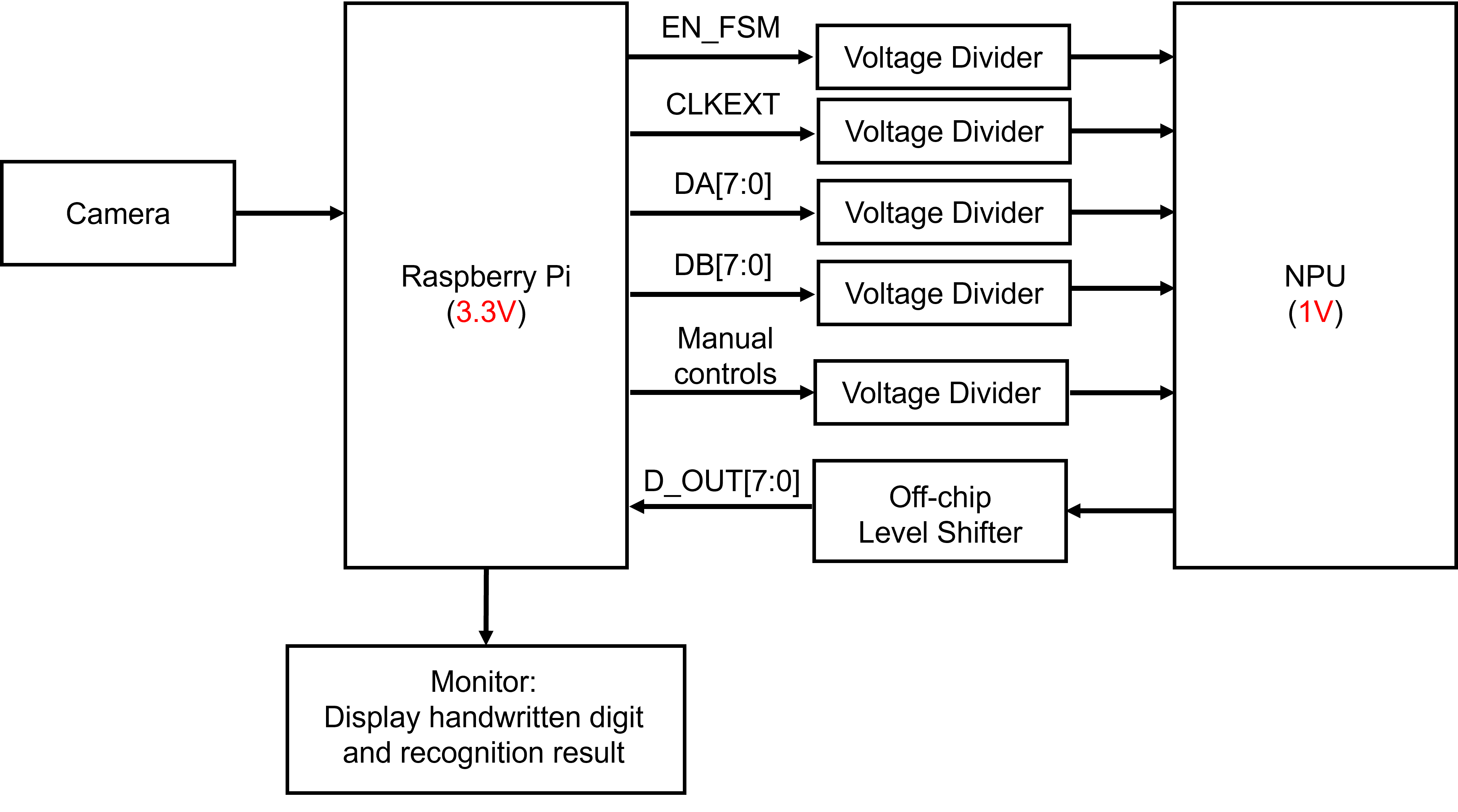
Figure 5. System Level Block Diagram(simplified)
in which the host controller is a Raspberry Pi (RPI) and it is connected to a camera for capturing images and a monitor for displaying the recognition results. We actually used this set-up for one of out demos (Demo1: RPI+NPU) and the detail of this system will be explained in the demo tab.