
Testing Results
We covered lots of testing results in Demo 1:RPI+NPU and Demo 2:FPGA+NPU. Those results focus on chip functions, system-level performance and algorithms. This tab includes more performance summary about NPU solution, and some electrical analysis.
NPU Reliability
For reliability validation, we used our RPI+NPU setup to run the inference process for 100 images and totally we obtained 4200 neurons. Each neuron is derived from hundreds of MAC operations thus totally we've gone through thousands millions of MAC operations. As shown in Figure 1, every single neruon matched with our golden model from MATLAB, indicating that our computation mechanism is trustworthy.
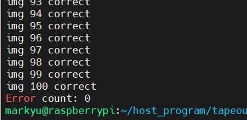
Figure 1. Neuron validation test
Hardware Acceleration vs Software Solution
From the very beginning, we were trying to design a hardware accelerator to accelerate matrix multiplication process. We compared the computation speed of our NPU solutions to pure software solution on RPI. Essentially we created a C program on RPI that replicates all operations that NPU would execute to complete one inference and we measured the duration of it. The comparison results are shown in Figure 2. Using a 1.2 GHz ARM processor, RPI can complete the inference process in 0.14 ms with pure CPU computation. In constrast, for our FPGA+NPU solution, we need 0.36 ms to complete one image under the highest frequency we are supporting now. It appears that we just designed a "hardware decelerator", but the CPU computation is only 2.5x faster using a 192x higher frequency, indicating that the NPU is doing the computation in a much more efficient way. The performance difference mainly comes from frequency difference.

Figure 2. Hardware and software solution comparison
Electrical Parameter Measurement
Nominal supply voltage to our chip is 1.0V. We varied VDD to see whether the chip can still operate properly under a smaller voltage. It has been validated that the chip is fully functional between 0.8V to 1.2V when operating at 6.25MHz. Higher voltage has not been tested since it could damage the chip. The chip started to generate random/unpredictable results when VDD is lower than 0.8V, as the transistors become too slow.
Our nominal frequency is 10 MHz but using the current PCB it will stop working at 8.33 MHz or higher. We suspected this is a system-level VDD problem because we observed a very large VDD ringing on PCB as shown in Figure 3. We used a 2-layer PCB for our NPU thus there is no VDD plane for minimal inductance. We have 0.1uF and 4.7uF decaps for NPU but it seems that the VDD ringing has high frequency components (tens of hundres of MHz), so smaller capacitance may be required to filter this ringing out. We observed that the outputs from NPU become non-deterministic when frequency is higher than 6.25 MHz as shown in Figure 4 and 5. Large VDD ringing could cause random bit flips inside the chip thus results are different each time. We may design another version of PCB in future to address this issue.
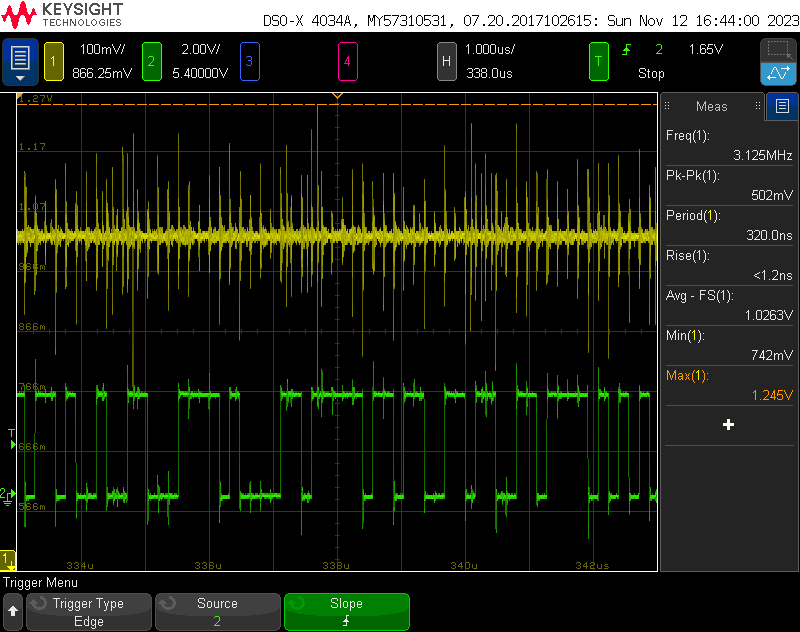
Figure 3. Yellow: VDD, Green: One input signal
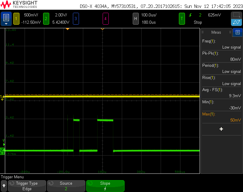
Figure 4. Green: One output port of NPU at 8.33 MHz (case 1)
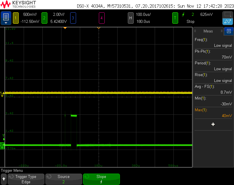
Figure 5. Green: One output port of NPU at 8.33 MHz (case 2)