
Chip Demonstration
This project culminated in a demonstration of the chip functionalities to engineers from Apple Inc. and the rest of the class. The demo is presented in the first minutes of the video posted in the Introduction section.
C Program
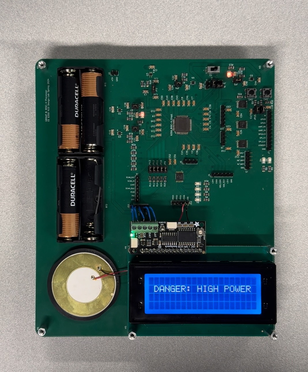
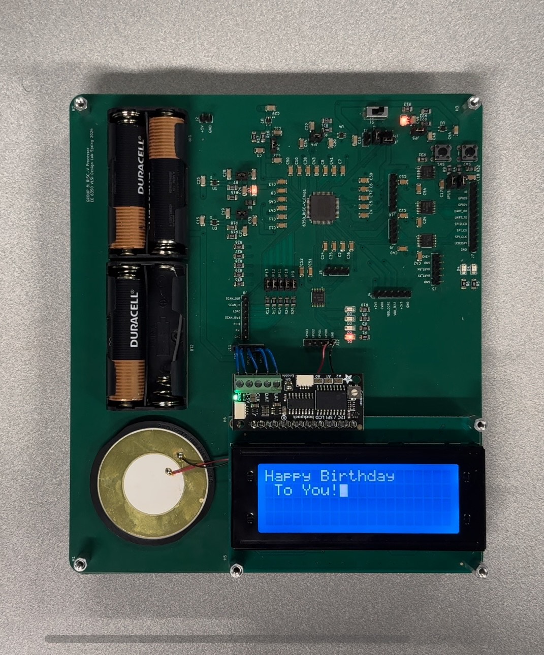
For this demo we created a C program that uses the ALU of the processor as well as all the communication peripherals implemented on the SoC. In particular, the main() function starts with an initialization sequence which includes some LED toggling as well as printing a welcome message on the LCD screen, as shown in Figure 25. We also added a brief joke that displays a high power warning and toggles the LCD on and off (Figure 31), it disappears after few seconds and the normal operation continues.
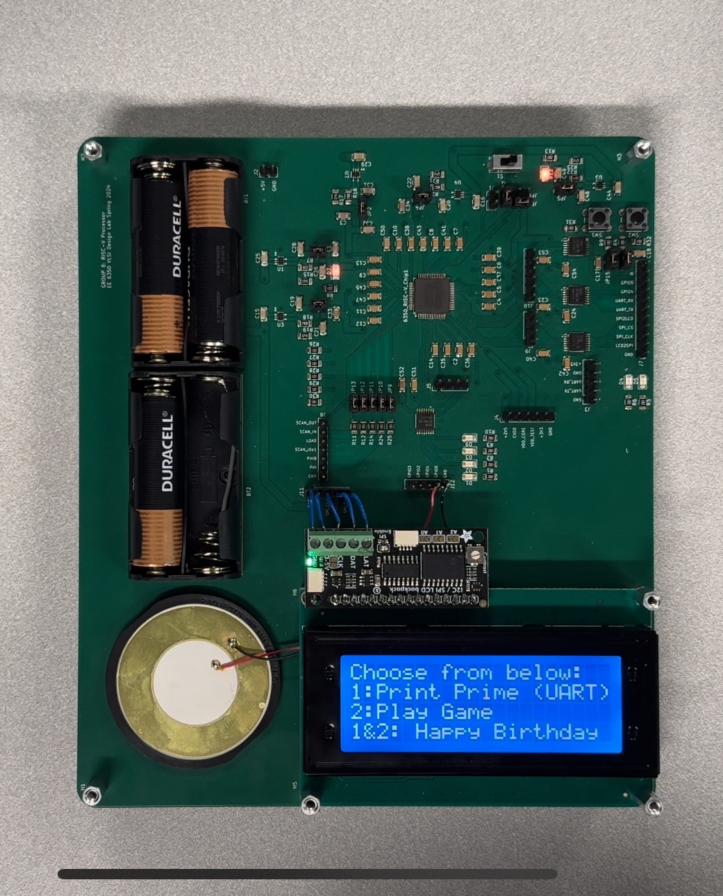
After that, it displays a menu with three different options which the user can select by pressing one or both buttons (Figure 32). Each option executes a different function/subprogram whose purpose is to demonstrate the functionality of a different communication peripheral.
UART
The first option executes a function which polls over the input GPIOs (connected to 2 keys on the PCB) and, as the LCD display explains (Figure 33), for every button press it prints the next prime number on the terminal of a local PC (Figure 34) connected to the chip through its UART interface.

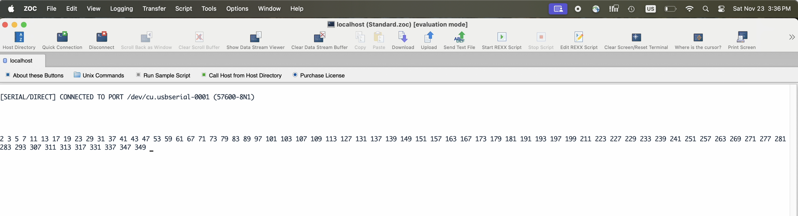
The C function starts by initializing the UART interface. It configures the clock divider inside the UART module to accommodate the selected baud rate of 57600, at a frequency of 59.98 MHz (the required divider value is 0x000007DA). It also sets the UART operation mode as well as some new line characters to clear the terminal. Then, every time the button is pressed, the next prime number is calculated by dividing every prime number that was found before through the next number, until a a new prime number is found. The other button brings the user back to the main menu.
SPI
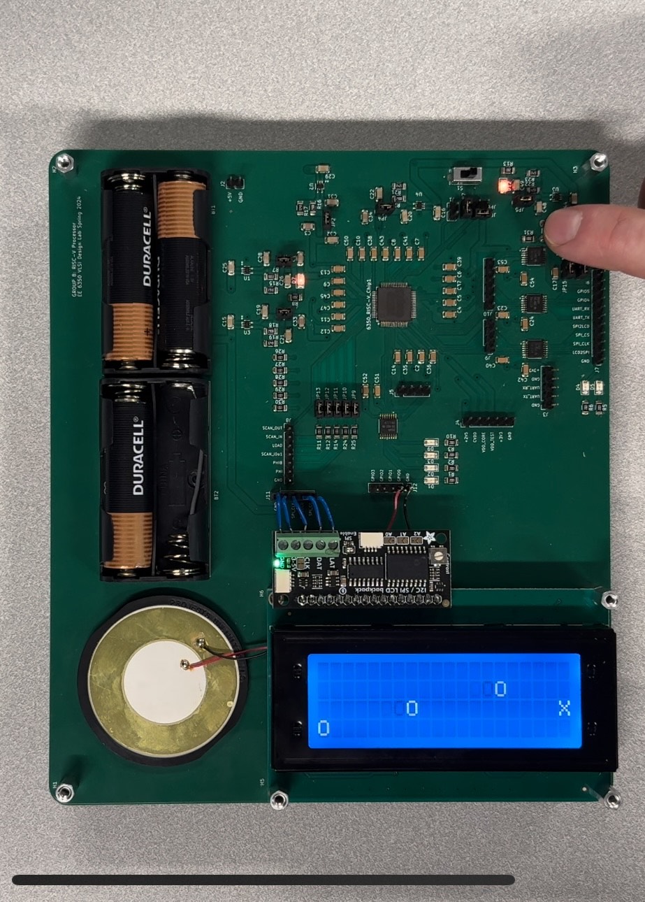
The second option showcases a more advanced use of the SPI interface, where the user is able to play a simple game and interact in real time with the processor. As shown in Figure 35, the display generates a pointer X that represents the player and multiple obstacles O that are moving towards the player X. The user is supposed to use the GPIO keys to control the movement of the player X and avoid the incoming obstacles. To make this functionality possible, the game logic had to be designed and appropriate control of the LCD display had to be ensured.
On the one hand, the game logic was implemented from scratch. On the other hand, we needed to implement functions to properly write to the LCD display. These displays are not build for custom designed chips, but rather for common microcontrollers such as the Arduino. The manufacturer Adafruit provides libraries to handle the access, so in order to use it for our own purpose, we had to delve into the Arduino LiquidCrystal Library [6]. First, we had to use a basic Arduino example to see how we could use the LCD in a fun way for our demo. Then, we had to analyze all the code of this example from the high-level functions down to the most fundamental instructions that actually toggle the Arduino pins. Once we understood the entire flow, we re-implemented most of the available functions in our C system. Such functions allow us to turn on and off the display or implement a blinking cursor. This implemented library was used for all interactions with the LCD screen, which was solely controlled by the processor throughout the demo.
GPIOs
Finally, the last option runs a function that is mostly focused on demonstrating how the output GPIOs can be used. This function toggles the GPIO pins in a way that the connected piezo element produces the happy birthday tone. The toggling pattern actually implements different delays and durations for difference notes. At the same time, a LED is also blinking and as shown in Figure 36, the lyrics are synchronized and printed on the LCD display. We have also demonstrated that we can create a PWM just through software, with a large variety of frequencies.
Memory Loading
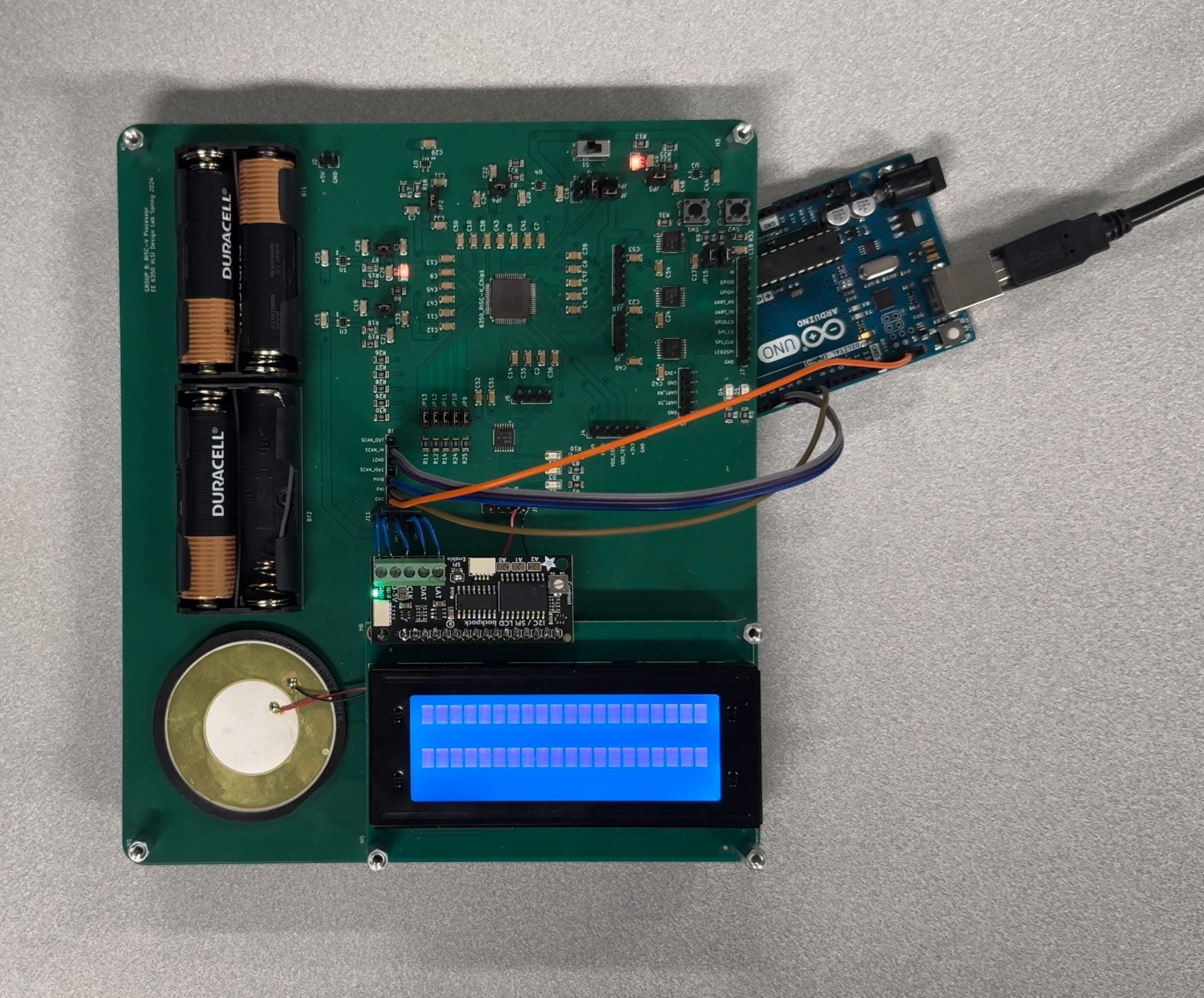
As discussed in section Software & Testing Flow, before deasserting the reset signal, the C program is loaded to the on-chip memory with the use of an Arduino, which drives the Scan Chain pins. The connection is shown in Figure 37. For the demonstrated program, the scan-in process takes about 2 minutes and once it is done, the Arduino can be disconnected and the PCB can be fully portable due to the use of battery cells for the power supply.
Code reference
Here you can find all the code that we used for the Demo.