DEMO1
Purpose
The goal of this demo is to showcase a real-time handwritten digit recognition system. The system processes handwritten digits captured via a website, preprocesses them on a Raspberry Pi. The FPGA and chip facilitate seamless integration and data flow within the setup.
This part is highly recommended to watch in our demo video for a clearer understanding of the workflow and system functionality.
Demo Setup
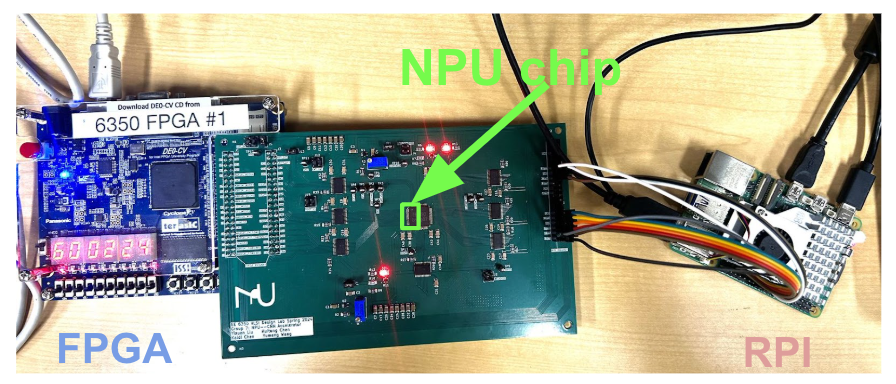
1. Hardware Components
- Raspberry Pi 5:
- Model: Raspberry Pi 5, 4GB RAM, 64-bit quad-core Arm Cortex-A76 processor at 2.4GHz.
- Used for capturing images, preprocessing data, and managing communication with the FPGA.
- FPGA:
- Model: Cyclone V 5CEBA4F23C7N
- 49K Programmable Logic Elements
- 3080 Kbits Embedded Memory
- 64MB SDRAM
- Functions as the controller for managing pixel data and clock synchronization with the Raspberry Pi.
- PCB with Chip:
- A custom PCB designed for interfacing the FPGA and Raspberry Pi with the onboard chip that performs specific signal processing tasks.
System Configuration
In this setup, a webpage is used as the interface for inputting handwritten digits. Users can draw digits using a mouse directly on the webpage. Once completed, the image is downloaded to the Raspberry Pi for preprocessing. The Raspberry Pi processes the image, resizing it into a 16x16 grayscale format suitable for further processing.
The Raspberry Pi and FPGA are connected via GPIO pins for data transmission. After preprocessing, the pixel data is sent from the Raspberry Pi to the FPGA, which acts as the master controller. The FPGA manages the timing and synchronization of data flow and sends control signals to the PCB. The PCB integrates the onboard chip (NPU) for additional processing, such as handling specific signal tasks or performing inference.
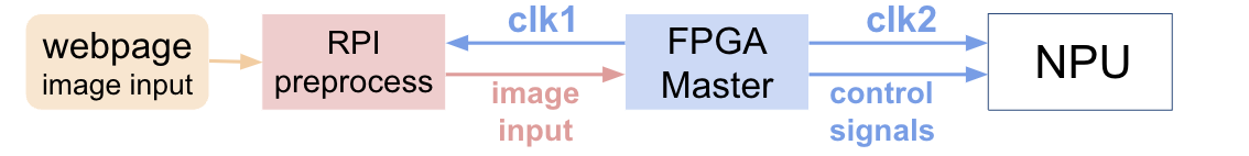
The entire system operates based on two clock domains: one clock (`clk1`) manages communication between the Raspberry Pi and FPGA, while a second clock (`clk2`) coordinates operations between the FPGA and the PCB. This dual-clock design ensures precise data flow and reliable performance, as illustrated in the Figure 2. system diagram above.
Demo Workflow
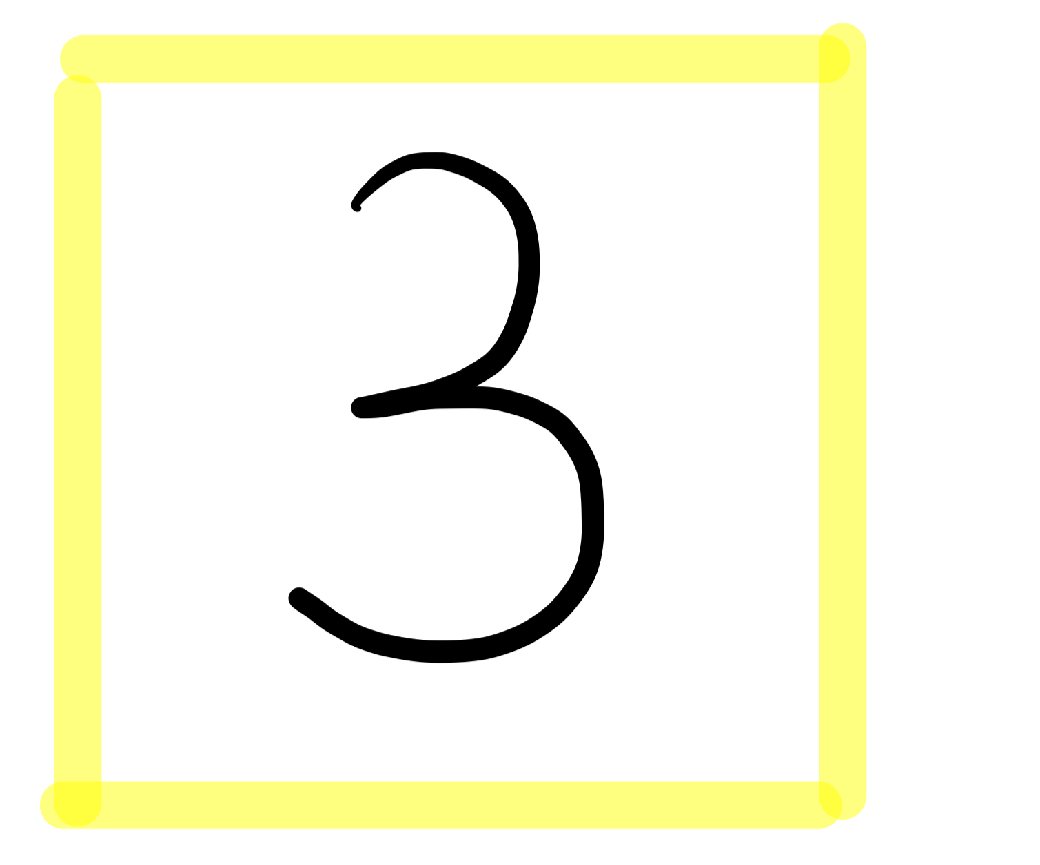
1. Image Capture
The webpage features a yellow box where users can draw handwritten digits using a mouse. Once the drawing is complete, the image within the yellow box is downloaded as a grayscale file to the Raspberry Pi. The downloaded image retains the drawn digit and is preprocessed by the Raspberry Pi, which resizes it into a 16x16 grayscale format suitable for further processing by the FPGA and chip.
2. Preprocessing
The Raspberry Pi preprocesses the downloaded image by extracting the digit from the yellow box and resizing it into a 16x16 grayscale format. This compact representation of 256 pixels is prepared for further processing and transmitted to the FPGA via GPIO pins.
3. Data Transmission
The FPGA receives the preprocessed 256 pixels from the Raspberry Pi and reorders them according to the input sequence required by the chip on the PCB. This ensures compatibility and optimal performance during the subsequent processing stages.
4. Chip Processing
The FPGA interfaces with the PCB, where the onboard chip executes the core processing. The chip hosts our CNN model, which processes the input pixel data to classify the handwritten digit. This step leverages the chip’s optimized architecture to ensure high accuracy and efficient computation.
5. Output
After processing, the classification result is transmitted back from the PCB to the FPGA. The FPGA then displays the predicted digit on its onboard LED lights, providing a clear and immediate visual representation of the result.
Results Demonstration
- Accuracy: The demo system achieves high prediction accuracy using the same weights and biases as the chip.
- Real-time Performance: The system processes and classifies digits within milliseconds of image capture, enabling a seamless user experience.