
System Overview
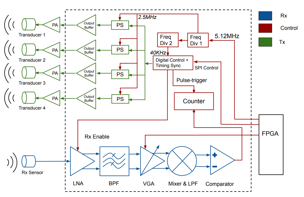
Figure 1. Ultrasound beamforming architecture.
The whole chip comprises of both transmitter and receiver systems. Within the transmitter, a Frequency Divider block is employed to takes a 5.12MHz clock from FPGA and produce a 2.56MHz and a 40KHz clocks for digital control blocks and phase shifters. The outputs of these phase shifters drive the off-chip power amplifiers, which subsequentially drive the TX transducers.
The receiver consists of LNA, HPF and LPF VGA, Mixer, and Comparator. The PGA gain is designed to be adjustable so that more gain can be obtained if the range of object increases. The presence of the reflected signal is detected at the Comparator output, which is fed into the Counter logic block to determine the distance from the system to the detected object.