
System Overview
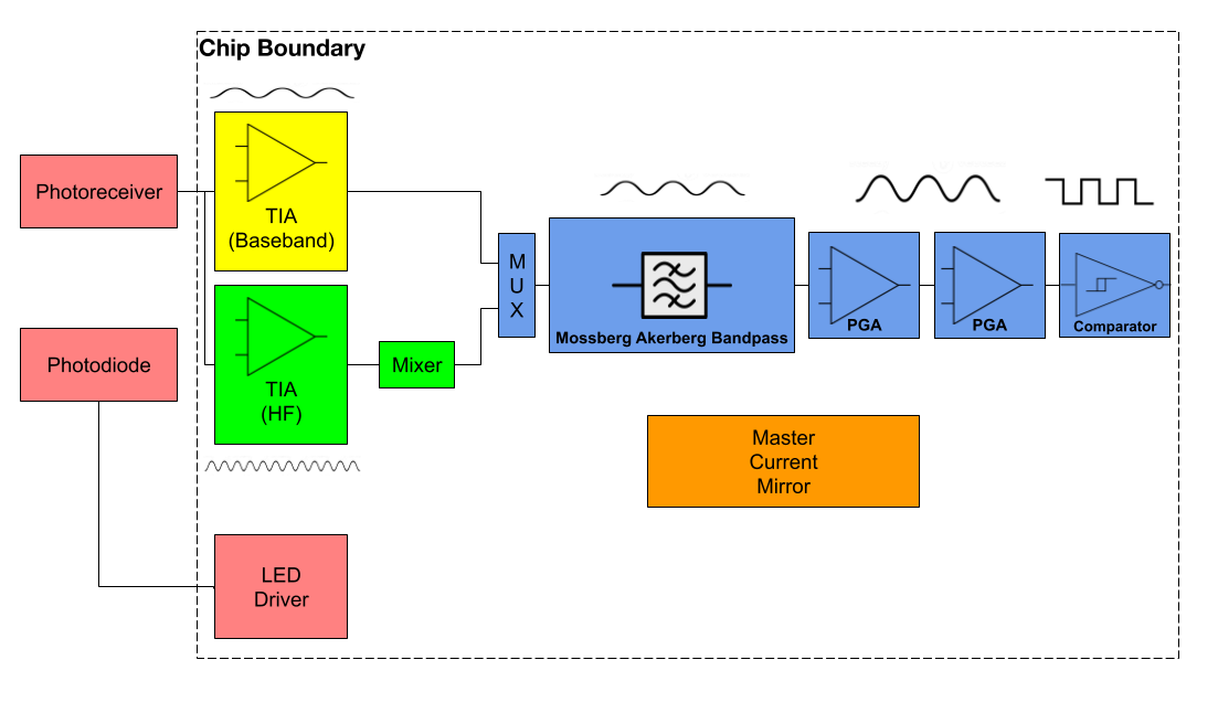
Figure 1. LP-PPG System Block Diagram
LP-PPG is an Analog Front-End (AFE) that extracts heart-rate via photoplethysmography and aims to minimize system power consumption by duty-cycling the sensor's optical source. The chip controls the full signal path, from generation of the driving signal sent to the LED, to preamplification, filtering, and A-D conversion. The chip features two parallel signal processing paths: Low Frequency (LF) and High Frequency (HF), set apart by their approaches to preamplification and the part of the native signal captured by each chain. After the LED Driver produces a high-frequency clock signal on-chip, a variable duty-cycled copy is driven to the LED. This results in a received PPG biosignal that is multiplied in the time-domain by a square wave with a variable duty cycle - the resultant frequency-domain convolution produces copies of the PPG signal of interest both at baseband (~1-3Hz) and surrounding the harmonics of the square-wave (e.g., at 999 & 1001Hz, for fc = 1kHz).
The LF signal chain consists of a standard PPG Analog Front-End, consisting of transimpedance amplification, bandpass filtering around the ~1Hz region, and amplification leading into 1-bit analog-to-digital conversion, which encodes the beat-to-beat interval in the time between rising edges, and can be easily converted to heart-rate on an off-chip microcontroller.
The HF signal chain takes advantage of the fact that, while the baseband signal intensity decreases linearly with LED Driver duty-cycle, the first harmonic of the square wave, and resultant PPG signals surrounding the received duty-cycled biosignal, does not. Thus, in the HF chain, the chip used a broadband TIA, passing both the baseband and the first few high-frequency harmonics, into a +1/-1 lock-in amplifier, driven by the 50/50 clock signal produced on-chip by the driver. This swaps the original baseband signal and the surrounding 1/f noise up into the kHz, where it is eliminated by subsequent filtering stages, and drops the duty-cycle independent first harmonic, and its lower surrounding 1/f noise, to baseband, which is then filtered-amplified, and extracted. At the cost of <1mW of power overhead, this signal chain produces marked improvements to SNR and allows LED driving power to be reduced from 50-100mW down to 5mW or less.
The goals of the system are outlined below:
Required:
- >= 95% Heart Rate detection accuracy
- < 5mW consumption for Analog Front-End (excluding LED Driver)
- Operational with continuous input and 50% duty cycle LED operation
- Limited (wearable) footprint
- Low (10%) duty-cycle operation
- Identify minimum viable LED pulse duty cycle (increasing Analog Front-End input power, reducing LED d.c. below 10%)
- <10 mW system power