
Chip Level Simulations
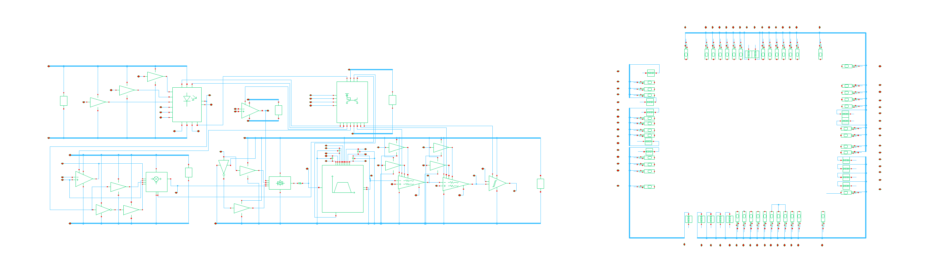
Figure 1. Full Chip with ESD Pads
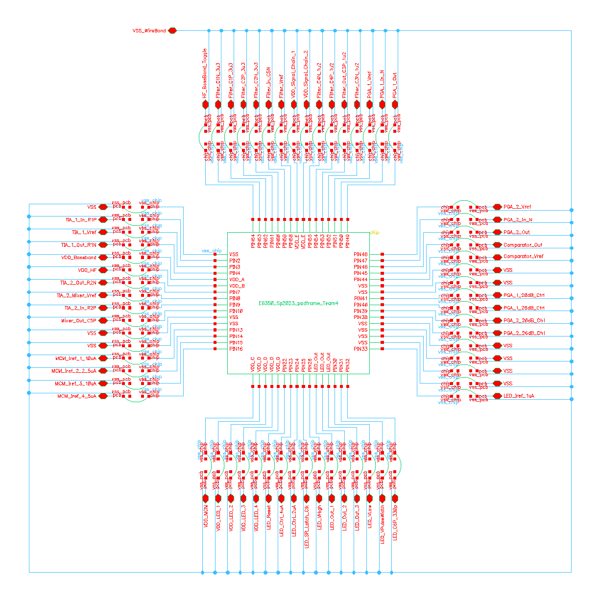
Figure 2. Wirebond Model of LP-PPG Chip
To ensure accurate simulations of the chip, the ESD pads and wirebonds were added to each pin. These models shown in the two figures above were used in verification to ensure that the chip behaved as expected.
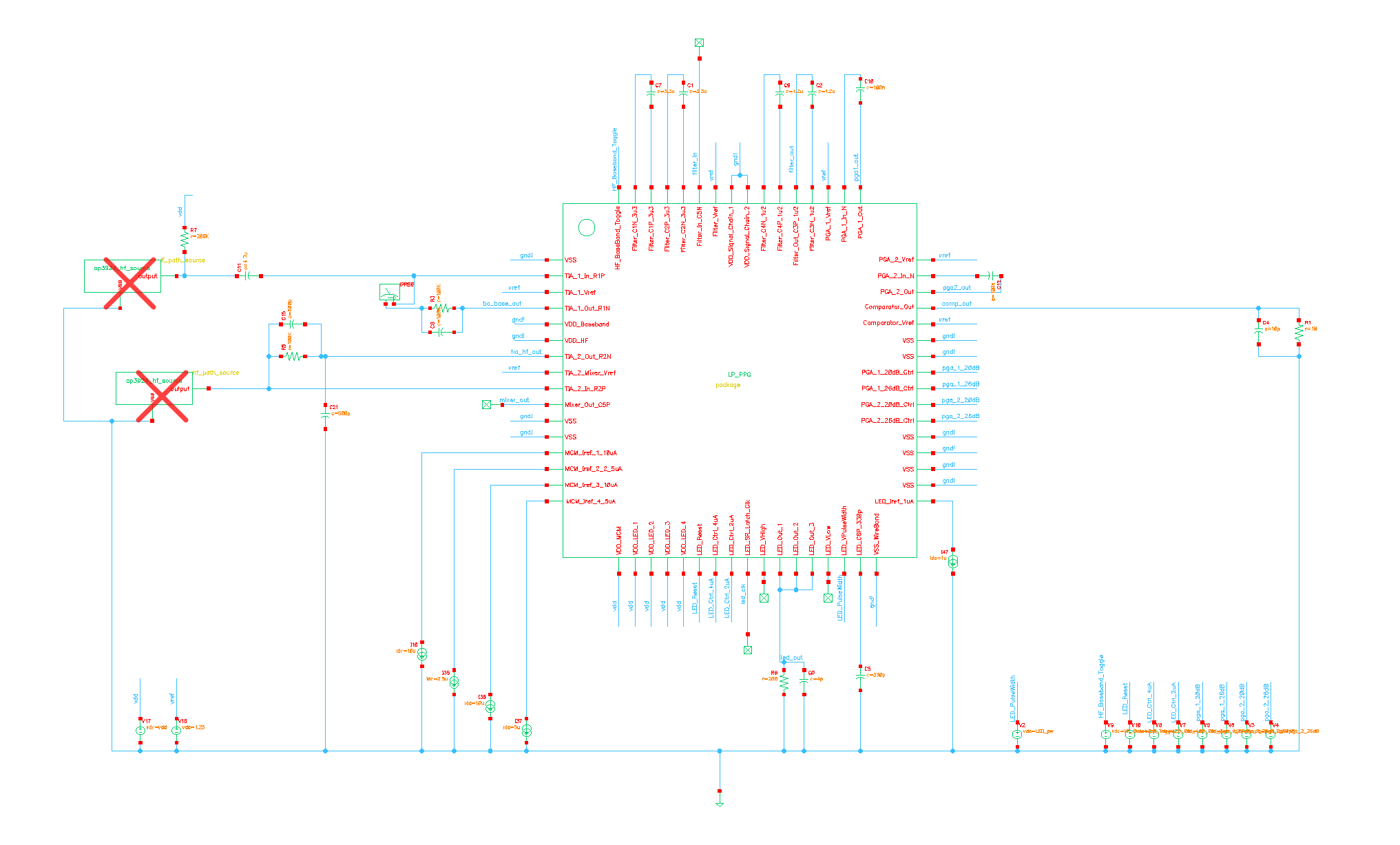
Figure 3. Testbench of LP-PPG
The figure above shows the testbench used to test the chip. Here, off-chip components and digital controls were included to emulate how the chip would be used after tape-out.

Figure 4. High Frequency Signal Model
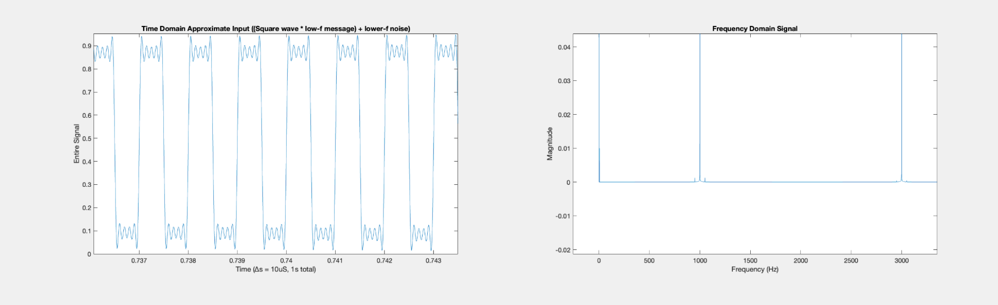
Figure 5. Mathematical Approximation of Native PPG Signal, Duty-Cycled
Once all blocks were finalized, the whole transceiver was tested in signal-in, signal-out simulations. In both cases, the native PPG signal, which would be produced by the receiver photodiode in the physical system, was assembled in MATLAB and fed in as a custom current source. The generated signal was built to mimic a 50% duty-cycled native photoplethysmograph, including a DC term, a signal of interest (1Hz), and harmonic copies of the DC current and signal-of-interest at a principle clock frequency and the first five odd harmonics with amplitude scaling proportional to the frequency-domain formula for a time-domain square wave.
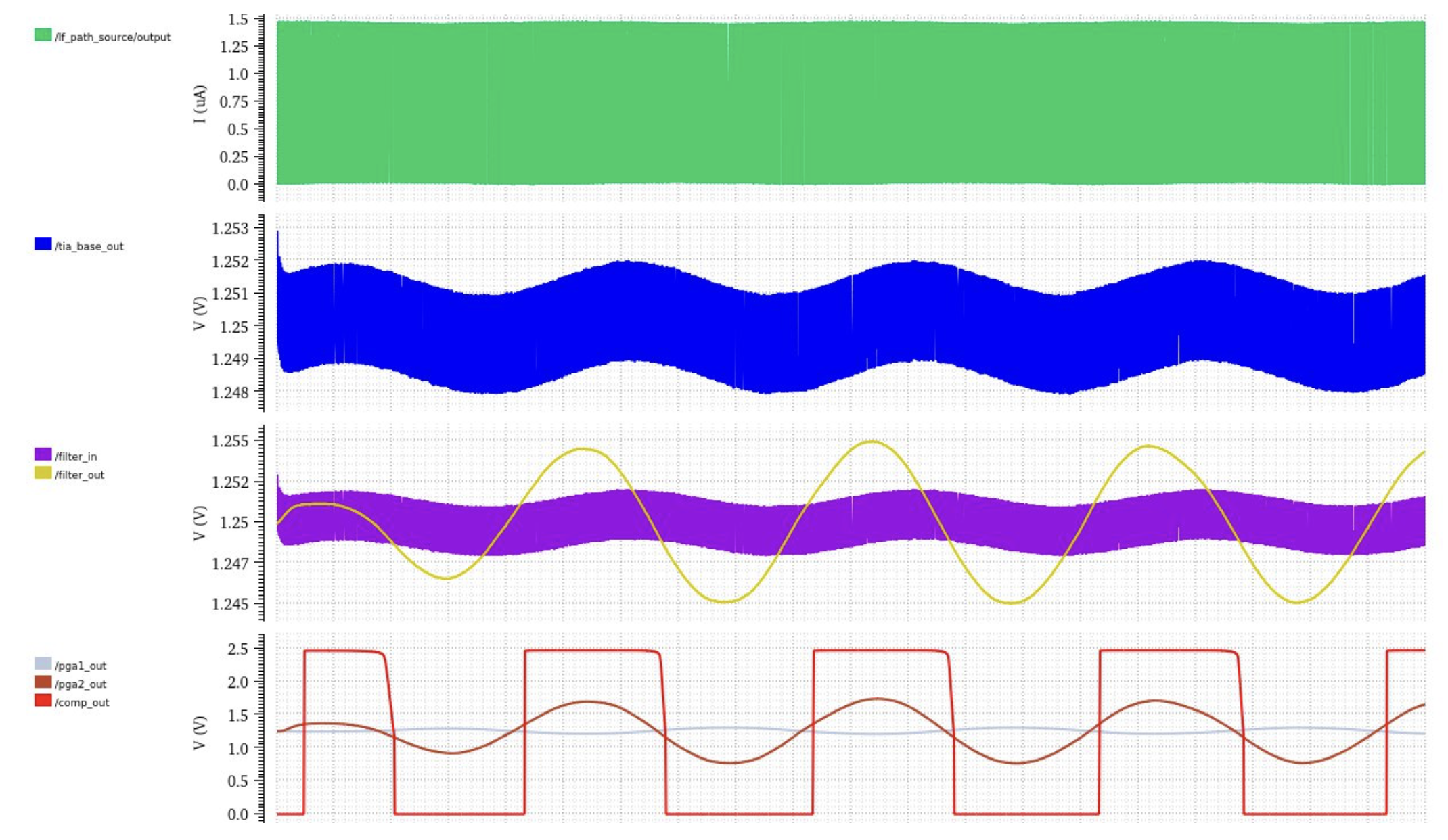
Figure 6. LF Chain, Signal In Signal Out, Lowest Gain Mode
When fed into the LF signal chain, the simulations show the TIA recovering the faint signal of interest with some clock-fundamental feedthrough. This high-frequency interference is attenuated by the filter as the signal of interest is boosted, and this mV-level signal is greatly amplified by the PGAs and converted into a 1-bit digital signal by the comparator.
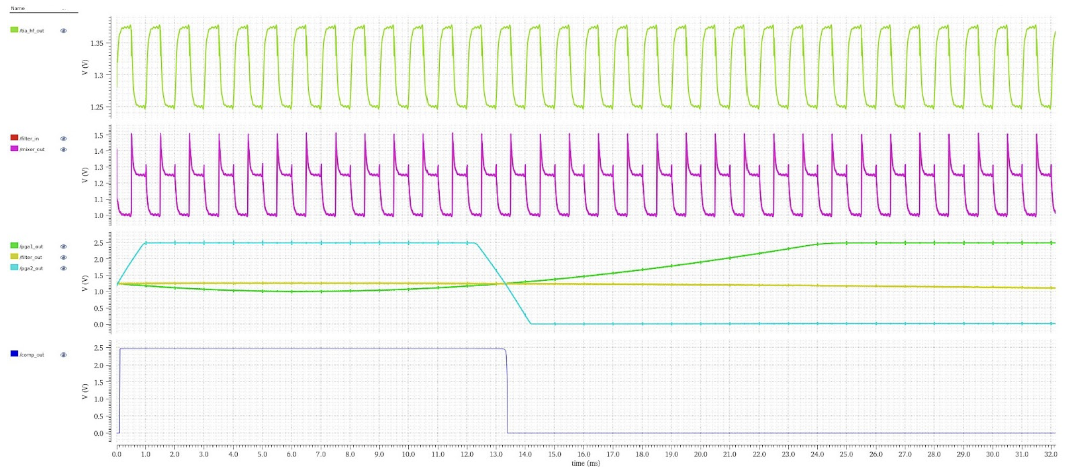
Figure 7. HF Chain Signal In Signal Out, Lowest Gain Mode
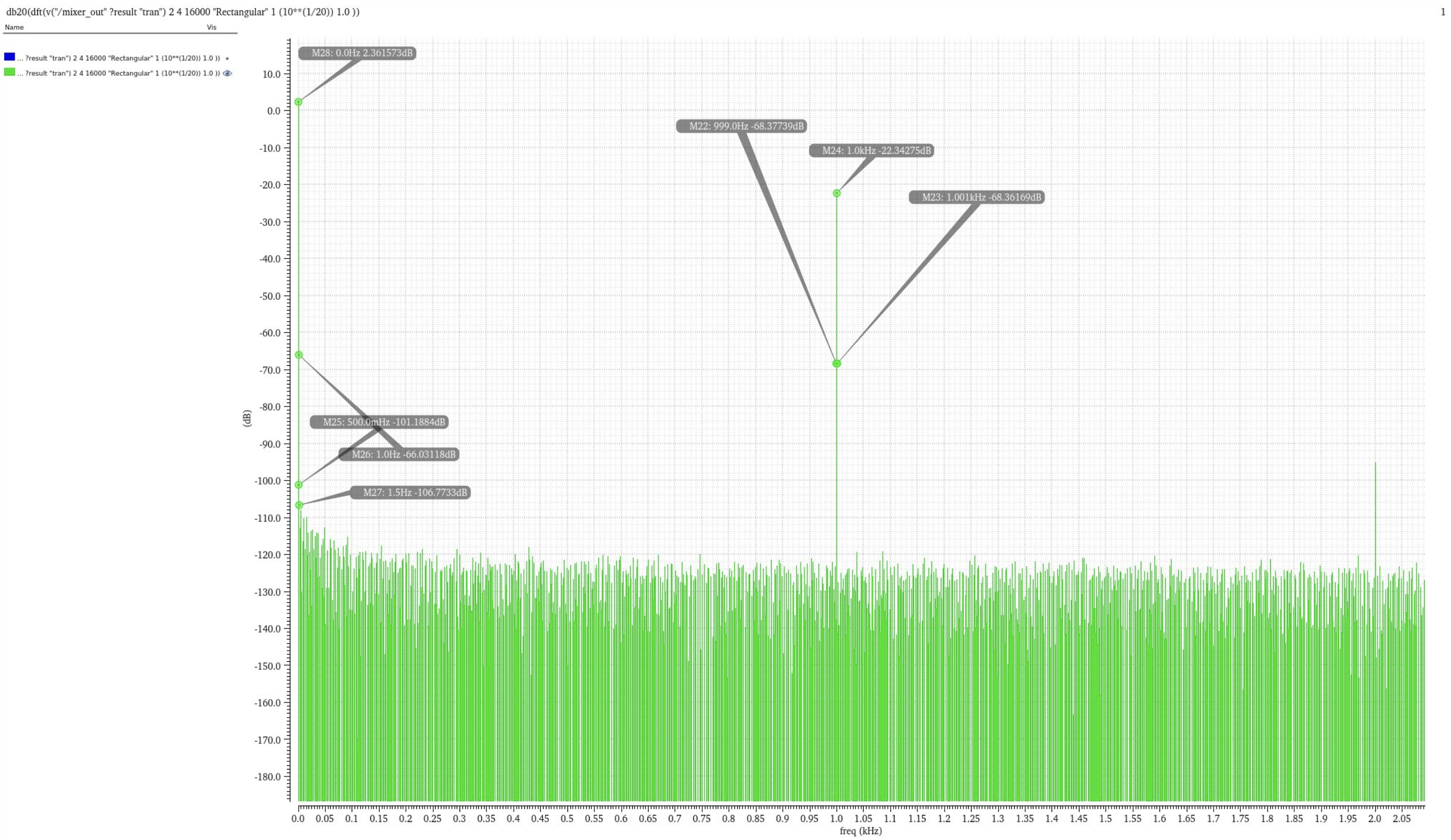
Figure 8. HF Chain DFT - TIA Frequency Domain
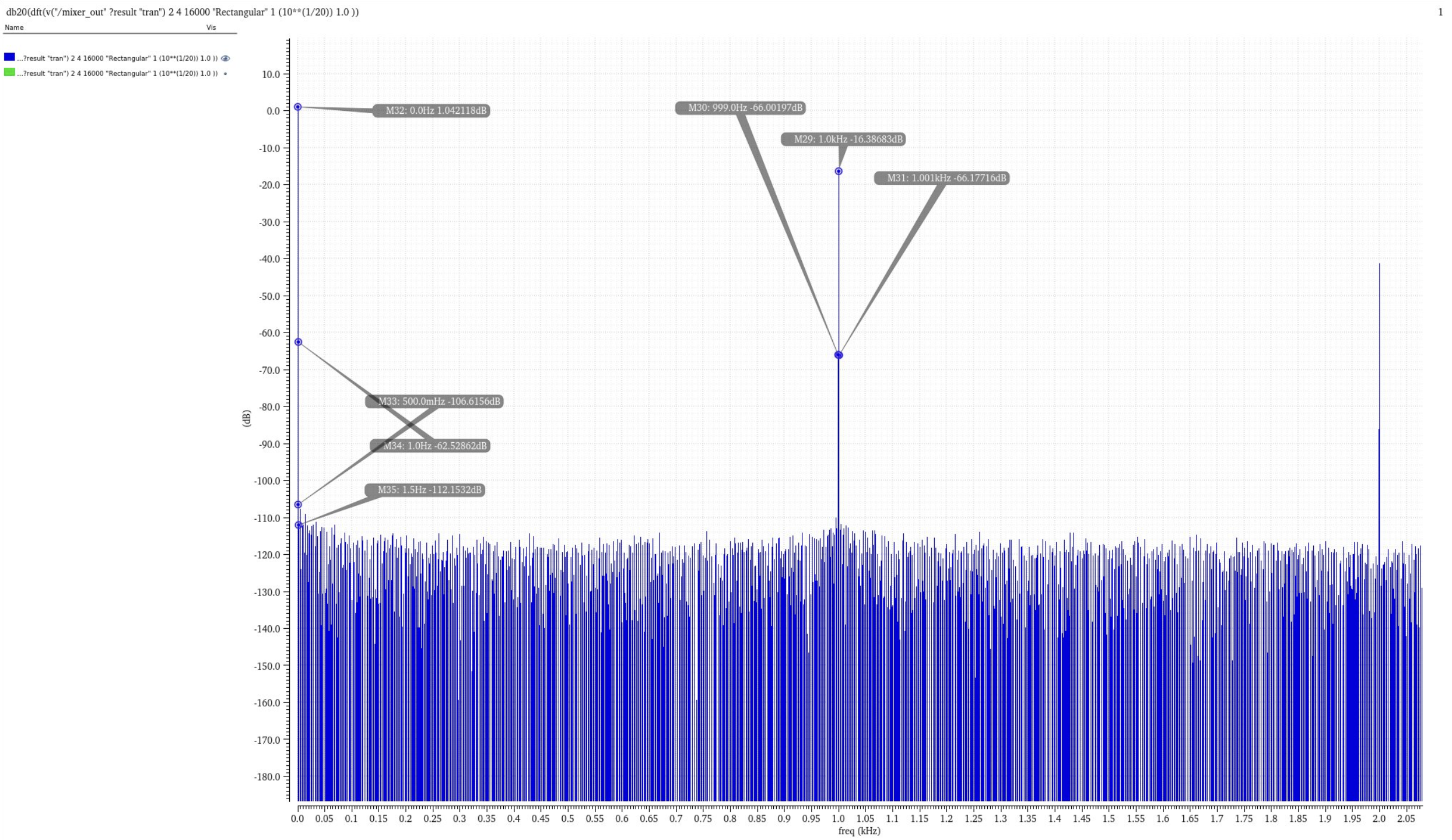
Figure 9. HF Chain DFT - Mixer Frequency Domain
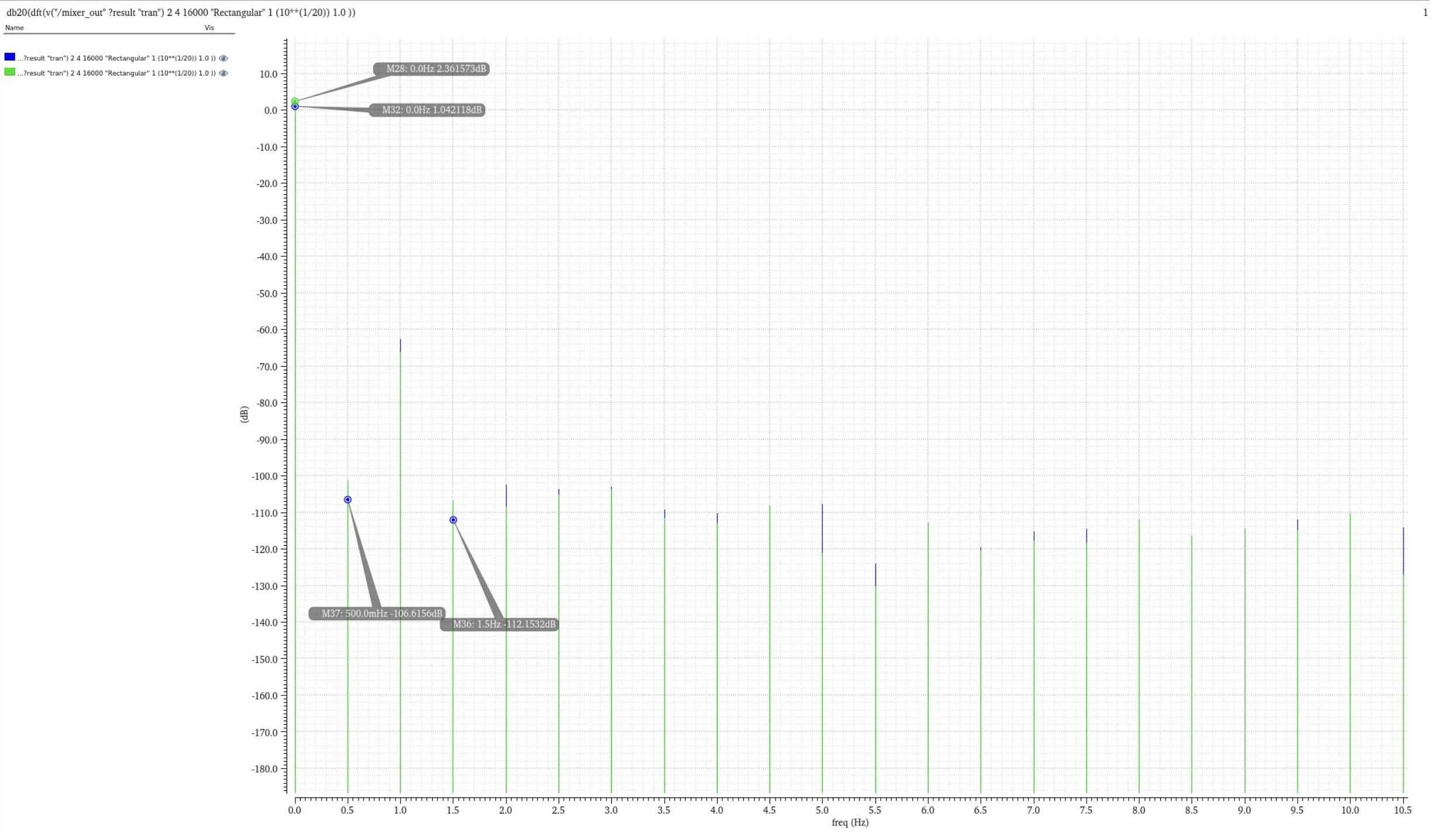
Figure 10. HF Chain DFT - Noise Comparison
In the HF chain, the received signal enters the +1/-1 mixer. The signal fed to the mixer contains a down-mixed 1Hz component in addition to the up-mixed original signal group, but the filter and PGAs do successfully extract a 1Hz output for the comparator to extract HR from. A DFT of the mixer block's input and output signals during these simulations reveal successful noise-shaping, although the noise floor rises by virtue of introducing more stages to the signal chain, the 1/f noise of baseband is successfully moved up around the clock fundamental, and the remaining 1/f profile, produced by the mixer itself, is lower than the spectral noise surrounding the PPG signal in the original LF chain. This confirmed the fundamental operating principle of the HF chain (noise-shaping for SNR improvement), and further characterization of the HF's chain impact was performed during post-silicon validation.