
Introduction
Welcome to the homepage of Team 04: Low-Power Photoplethysmography (LP-PPG)
The LP-PPG chip was developed as part of Columbia University's VLSI Design Lab (ELEN E6350) course, taught by Professor Peter Kinget in Spring 2024. The VLSI Design Lab aims to expose students to the entire IC design flow, from pitch development, to custom schematic design and physical design, to tape-out and post-silicon validation over the course of two semesters. This project was made possible by Apple Inc., who sponsored the fabrication and packaging of the chips.
Figure 1. LP-PPG Die Photo

Figure 2. Ideal PPG Signal in the Time and Frequency Domains
A Photoplethysmogram (PPG) is a biosignal useful for measuring heart rate. It tracks light intensity as a result of reflected light from a human finger or wrist. Each time the heart beats, blood vessels contract, causing light absorption to spike. Thus, the frequency of these spikes directly maps to heart rate.
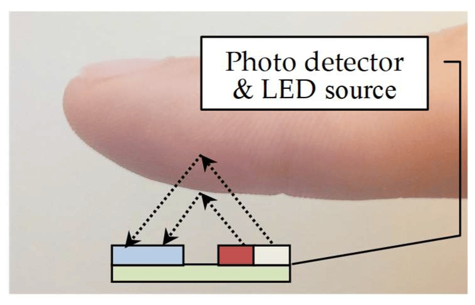
Figure 3. Application to Measure PPG Signal
In modern battery operated wearables that incorporate PPG sensors, power consumption is a major focus of the design. When looking at a PPG system as a whole, the majority of the power consumption comes from the optical sensors used to interrogate the PPG signal. The easiest way to reduce the overall power of the optical sensors is to duty cycle the Infrared LED. However, duty cycling the LED reduces the overall amount of signal that is received, lowering the signal-to-noise ratio (SNR). LP-PPG aims to use duty cycling to dramatically reduce overall optical receiver power coupled with lock-in amplification to improve SNR, by upconverting the PPG signal through the optical receiver and downconverting the signal to lower the noise floor.