System Overview
When it comes to electronic power amplifiers, there are several types we can choose from. Class A, Class B, and Class D amplifiers are all common types of electronic amplifiers, but they operate differently and have different characteristics. Class D amplifiers are the most efficient type of amplifier, as they use pulse-width modulation to switch the power transistor on and off very quickly, which reduces power loss. The Class D amplifiers' efficiency can reach above 90%, which is significantly larger compared to Class A(20-25%) and Class B (50-60%).
Figure 1 shows a basic Class-D amplifier structure. The audio signal input is compared with a high-frequency triangle wave, to produce a PWM signal. To properly drive the large output driver, the gate pre-driver circuits are needed. Then after the output low-pass filter, the high-frequency components in the signal are filtered out, which leaves us with a loud and clear audio sound.
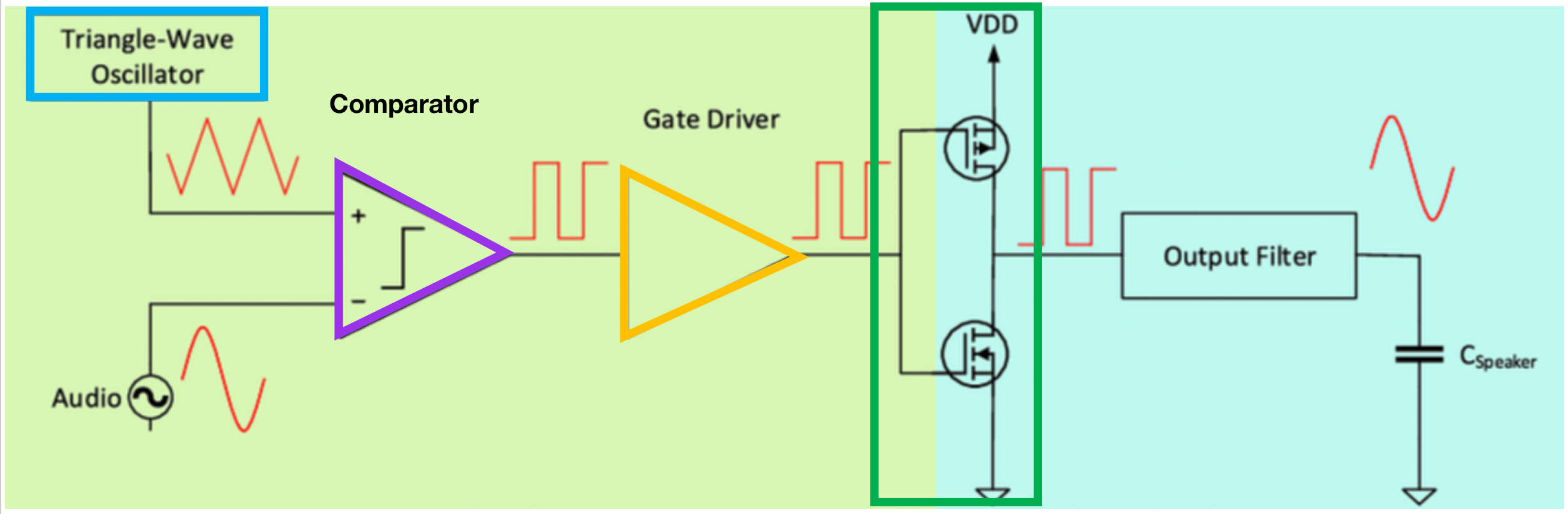
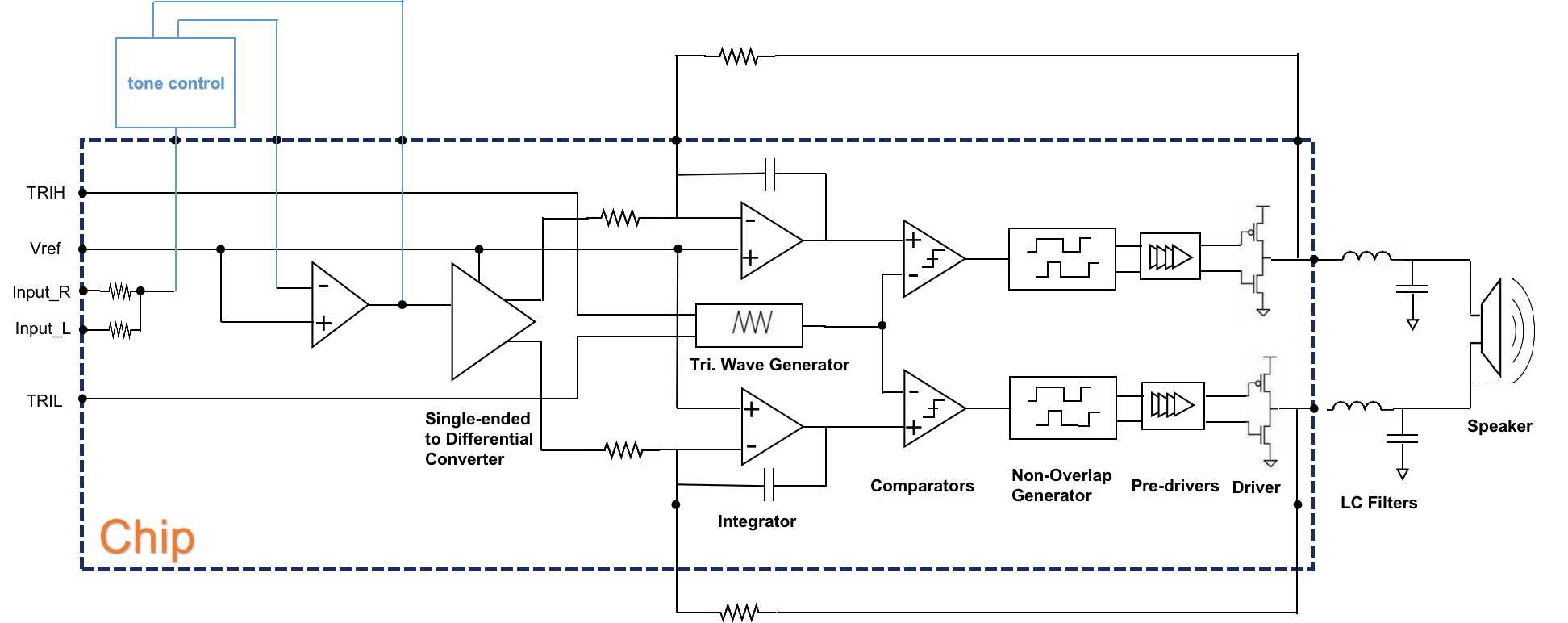
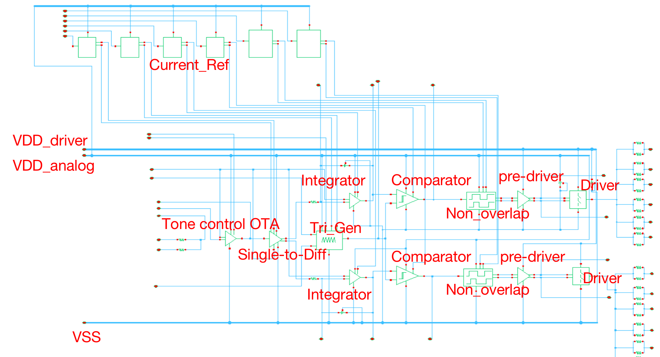
Figure 2 shows the block diagram of our overall structure.
The system adopts a pseudo-differential structure with signal flow proceeding from left to right. The left and right channel audio inputs are amalgamated and initially processed by the tone control system. The tone control system consists of an off-chip RC circuit and an on-ship OTA. Subsequently, the audio signal undergoes conversion into differential signals, which are then directed into integrators. The output from the integrator is compared with a high-frequency triangle wave to generate a pulse width modulation (PWM) wave. To introduce a dead time to the gate-driving PWM wave, a Non-overlapping generator is employed. To effectively drive the large output driver, a set of pre-drivers is also necessary. The output driver produces the ultimate differential output signals for the chip. Meanwhile, the output will also be feedback through feedback resistors to the integrators, and the integrators will integrate the error between the feedback and the input to make the system stable and accurate. This output will go through low-pass LC filters, which are off-chip, to drive a large passive speaker.