Simulation
OTA
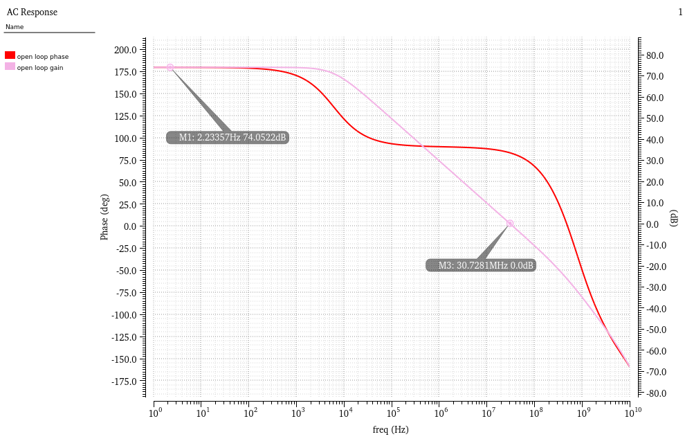
Figure 1 shows that our two-stage OTA has an open loop gain of 74dB and GBW of 30MHz under the TT corner.
System stability
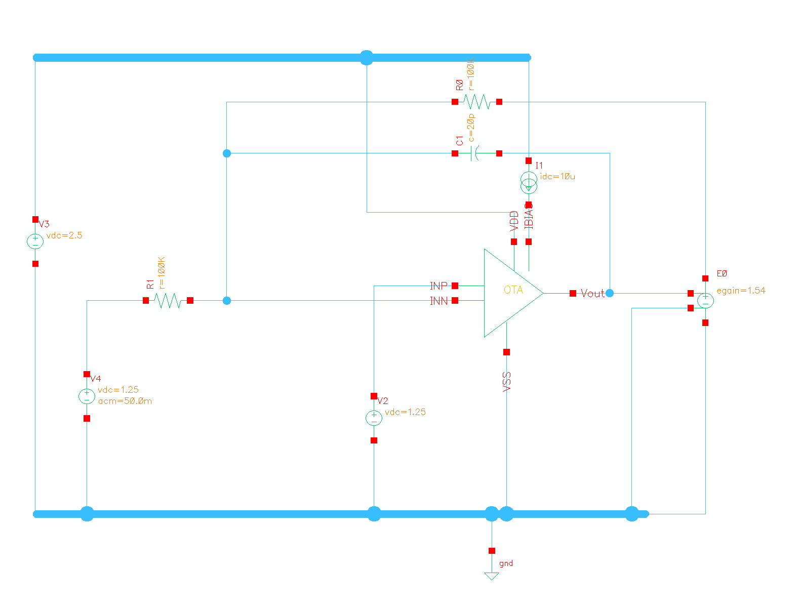
Figure 2 shows our whole system stability simulation. Because the comparator and driver are non-linear systems, we cannot simulate phase margin with these components. So, we model the comparator and driver as a vcvs with some delay, and the gain of the vcvs is VDD/Vm, Vm is the Vp-p of the triangle wave. Then, the phase margin of the system loop can be simulated at about 85.3 degrees.

Triangle wave generator
Figure 4 shows our 500kHz triangle wave generated by the triangle wave generator, and Vp-p is about 1.3V.
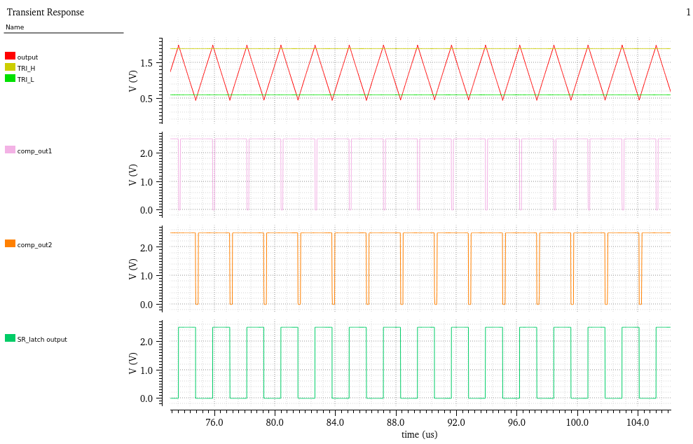
By changing the Iref, we can easily change the triangle wave frequency from 400 kHz to 600 kHz

Non-overlapping generator
Figure 6 shows the relationship between dead time and Iref in the non-overlapping generator. By changing the Iref, we can tune the dead time from 10ns to 45ns.

Top-level simulation
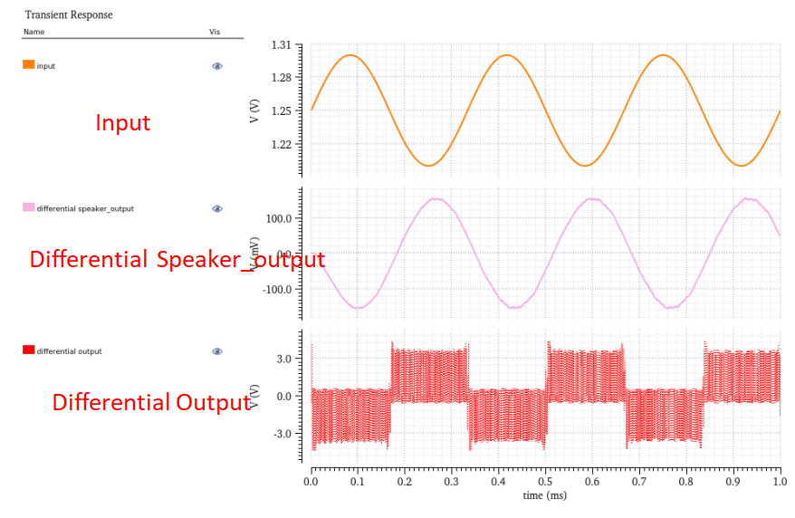
The end-to-end simulation results are shown below. The input sinusoid wave is successfully reproduced at the output.