
Testing
Overall Operation and Performance
The chip is functional and accurate. The clock chip/PCB can correctly display time and count time at precise speed (accuracy > 104, please see ACCURACY section below for more details). And we can set the clock to a specific time and start counting, just like a normal digital clock.
The alarm/time modes are all fully functional. When the time comes, the chip can successfully send a signal to start the buzzer, which can also be turned off by users.
| Accuracy | Power | Input Voltage (1V domain) |
Input Voltage (2.5V domain) |
|
|---|---|---|---|---|
| Typical | > 104 | < 150 μW | 1V * | 2.5V |
| Range | N/A | N/A | 0.65V ~ 1.1V * | 2V ~ 2.65V |
Table 1: Chip Specs
*Note: Due to the hold-time violation discussed in the section below, the actual input voltage rage for 1V domain is 0.65V ~ 0.85V, and typical voltage is 0.8V.
Power Consumption
Our chip has 2 voltage domains: 1V for digital logic, and 2.5V for LED/buzzer driver circuitry. 2.5V on PCB also supports peripherals like LED and buzzer. For the whole PCB system, typical power consumption are as follows:
- 1V domain: ~ 65 μW
- 2.5V domain: ~ 225 mW (>90% is consumed by LED)
The chip consumes less than 150 μW power under typical operations. Overall speaking, our chip is pretty power efficient.
Accuracy
1. Single Board Testing
Multiple tests indicate that the whole clock system is 1 second slower every 10 hours, which is equivalent to an error ratio of 2.8×10⁻⁵. Our testing result of crystal's error ratio is around 2.5×10⁻⁵ (the crystal's frequency is around 25ppm slower than rated, equivalent to 1 second slower every 11 hours). Which means the chip's accuracy is almost as good as the crystal.
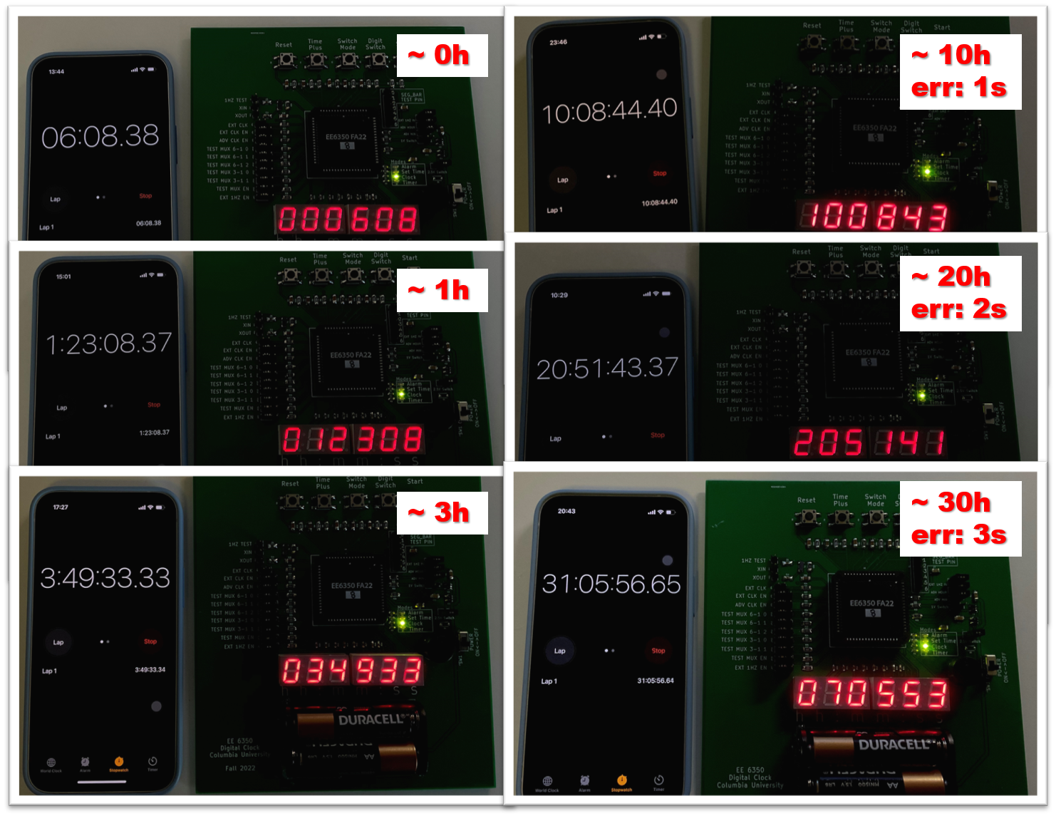
Fig. 1: Accuracy Test
2. Boards Comparison
We also tested the accuracy variation between different chips/systems. All the boards demonstrate an accuracy better than 1 second error every 10 hours. We also observe some variations among different different systems, which may be caused by process variation.
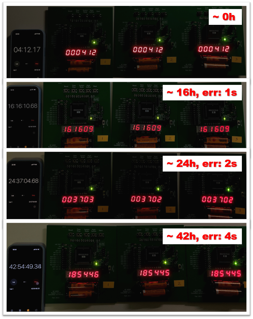
Fig. 2: Accuracy Test
Discussions
1. Hold-time Violation
Even though we verified the circuits across PVT corners, there are still hold-time violations in the chip. We observed the timing violation in two blocks: the frequency divider, and the display driver, which are marked in green in Fig. 3. Both blocks have short combinational logic delays between flip-flops, which are most susceptible to hold-time violation (due to process variation, clock skew, etc.).
Timing violation is observed at 1V power supply. When reducing the power supply to around 0.8V, which slows down the circuit, the circuit starts to function properly. Another technique to resolve hold-time violation in post silicon phase is increasing temperature, but it's not a convenient method for a portable device. Therefore, the board is re-configured to provide 0.8V to the chip instead of 1V, which is the configuration for all the tests.
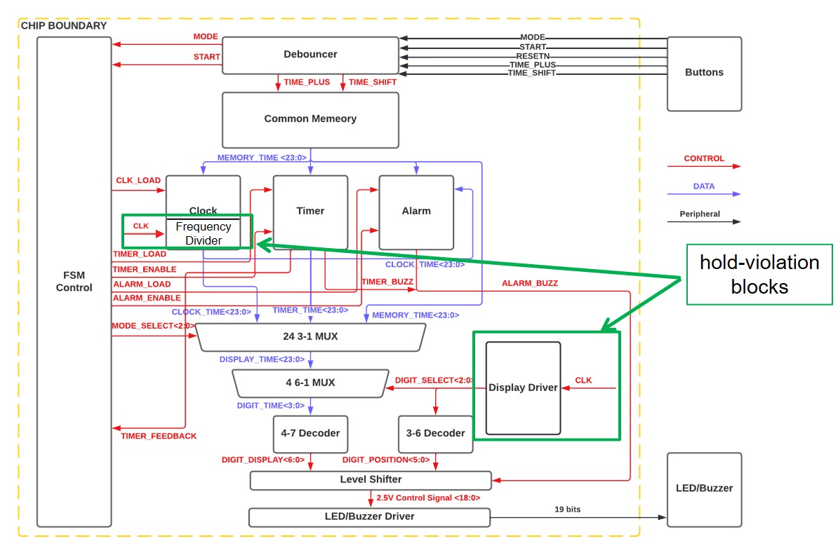
Fig. 3: Hold-time Violation Blocks
2. Power-on Issue
When powering on the PCB system and the chip, the on-chip registers will start in some unknown states/values which can cause some troubles. For example, on PCB's buzzer will keep alarming after powered on, which maybe caused by buzzer register unwanted falling into 1 during powering on. Ideally, it would be better to power on the chip to a know state. An additional Power-on-Reset (PoR) circuitry will be helpful to reset the circuit during power-on phase. It could be a further improvement in this project.