
PCB System
Demo PCB Overview
We designed the PCB in KiCAD software. The dimension of the PCB is around 13cm × 14cm.
This PCB has full support to run and test the Digital Clock chip. And it can operate as a stand-alonesystem, with a power supply source of 2 AA batteries. This PCB includes the following main components:
- Power source: 2 AA batteries
- 2 power converter ICs (LDO) to generate 1V and 2.5V
- 32.768 kHz crystal
- Push-button switchs for control
- 6-digit 7-segment LED displays
- A buzzer
- Some headers and jumpers for configuration and testing
Some key block are discussed in the following topics.

Fig. 1: PCB Schematic
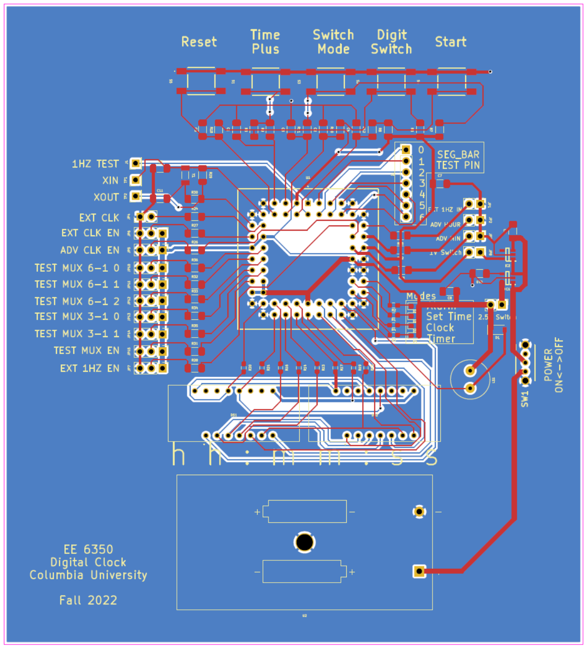
Fig. 2: PCB Layout
Power Circuitry
The PCB is powered by 2 AA batteries in series of 3V. The chip requires power supply of 1V and 2.5V, which are provided by 2 LDOs on PCB, as shown in Fig. 3.
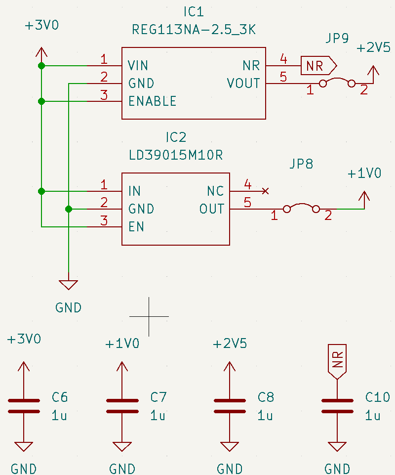
Fig. 3: Power Circuitry
Crystal Oscillator Circuit
This part of circuit generates the required clock source to feed the chip. A simple Pierce oscillator circuit is used here to generate 32.768 kHz clock signal.

Fig. 4: Crystal Oscillator Circuit
Push-button Switchs
Low-pass RC filter is used here to debounce the switch.
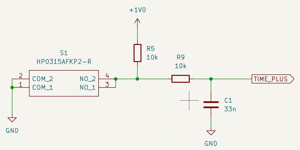
Fig. 5: Push-button Switch Circuit
LED Display
There are 6-digit 7-segment LEDs to display the time in hours, minutes and seconds. The additional dot-point is used to indicate digit selection.
We also add 4 seperate LEDs to indicate current mode/state.
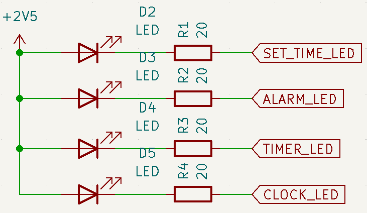
Fig. 6: State LED
PCB
Fig. 7 and Fig. 8 shows the whole PCB appearance.
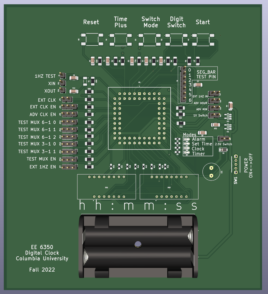
Fig. 7: PCB Illustration
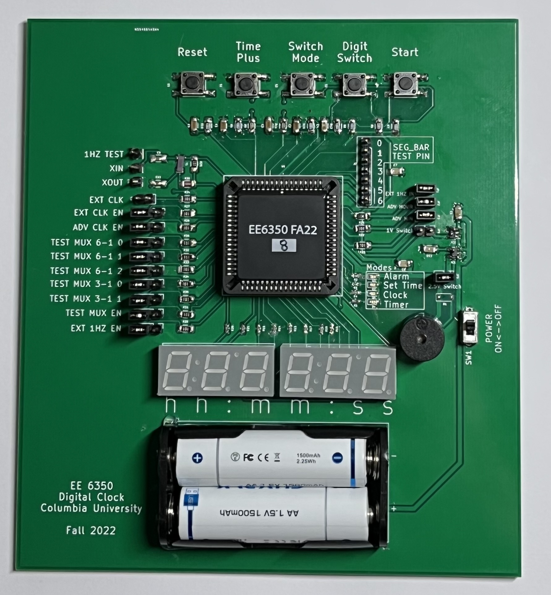
Fig. 8: Assembled PCB
Dimension: 13cm × 14cm