
System Overview
Digital Clock Introduction
Digital clock displays time digitally in hours, minutes and seconds, which normally consists of 6 digits. A common stand alone digital clock takes clock input from a crystal. We are using 24-hour format here, which counts time from 00:00:00 to 23:59:59.
Fig. 1: A Typical Digital Clock
IC Block Diagram
Block diagram of the chip is shown in Fig. 2. There are 5 main functional blocks on chip:
| Blocks | Description | Implementation |
|---|---|---|
| Clock | Counts current time | Synchronous up counter |
| Timer | Time countdown | Synchronous down counter |
| Alarm | Alarm | Comparator |
| Control | Takes inputs from buttons and control all blocks | State machine and multiplexers |
| Display | Drives external 7-segment LED with correct data | Level shifter and driver |
Table 1: IC Blocks Description
Logic block and driver are separated into 2 voltage domains:
- 2.5V: Level Shifter, LED/Buzzer Driver (drivers)
- 1V: All others blocks (logic blocks)
There are 4 operation modes to use. Each mode's functions are:
- Clock: Show current time
- Set Time: Set clock to a specific time with buttons and LED
- Timer: Use timer and display remaining time
- Alarm: Set alarm time and display
All modes can run in background and parallel.
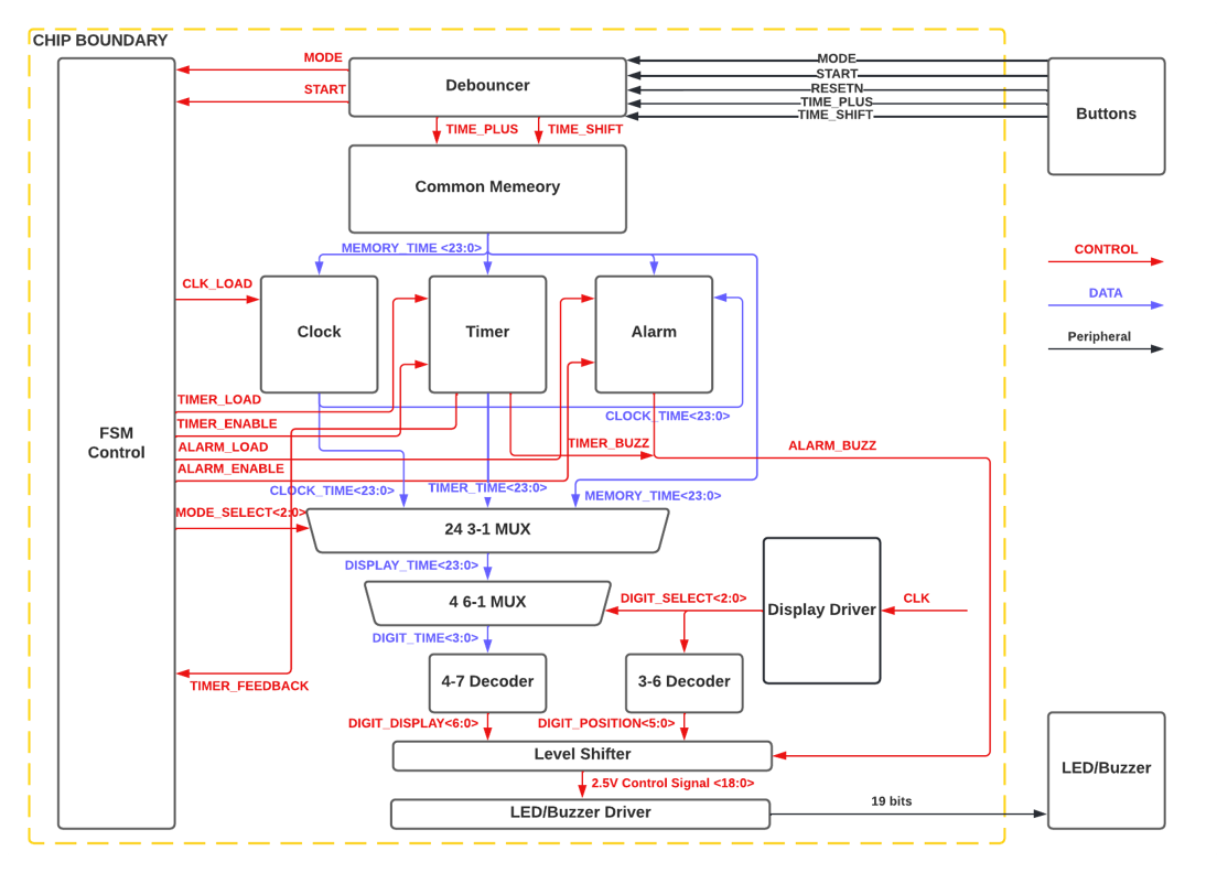
Fig. 2: Block Diagram of Digital Clock Chip