
System Overview
AM radio uses amplitude modulation to transmit analog audio information over the air on medium wave (MW) carrier channel frequencies. The AM radio band spans from 540 kHz to 1700 kHz -- classified as medium wave (MW) radio. Within the allocated frequency band, AM broadcasting channels are spaced at carrier frequencies 10 kHz apart.
The system block diagram is shown below. The AM channels are received by the ferrite loop antenna coupled to the input of the LNA. The LNA is designed to process input signal levels ranging from 50uV to 5mV in order to accommodate the entire range of broadcast power. Channel selection is accomplished by tuning the LO frequency such that the desired carrier is upconverted by the Mixer to a fixed intermediate frequency (IF) of 10.7MHz. The upconverted carrier at the IF port is routed off-chip to a high Q crystal bandpass filter with a fixed center frequency of 10.7MHz and 15kHz passband. The filtered IF signal is then routed back on chip to the input of an IF programmable gain amplifier (PGA). The PGA is made of four full-differential amplifiers with gain of 20dB, 20dB, 20dB, and 10dB in each stage and is controlled by four bits. The amplified AM signal at the output of the PGA is demodulated to the audio signal by a diode-based envelope detector. The baseband audio signal is routed from the output of the demodulator to an external power amplifier (PA) capable of driving a speaker.
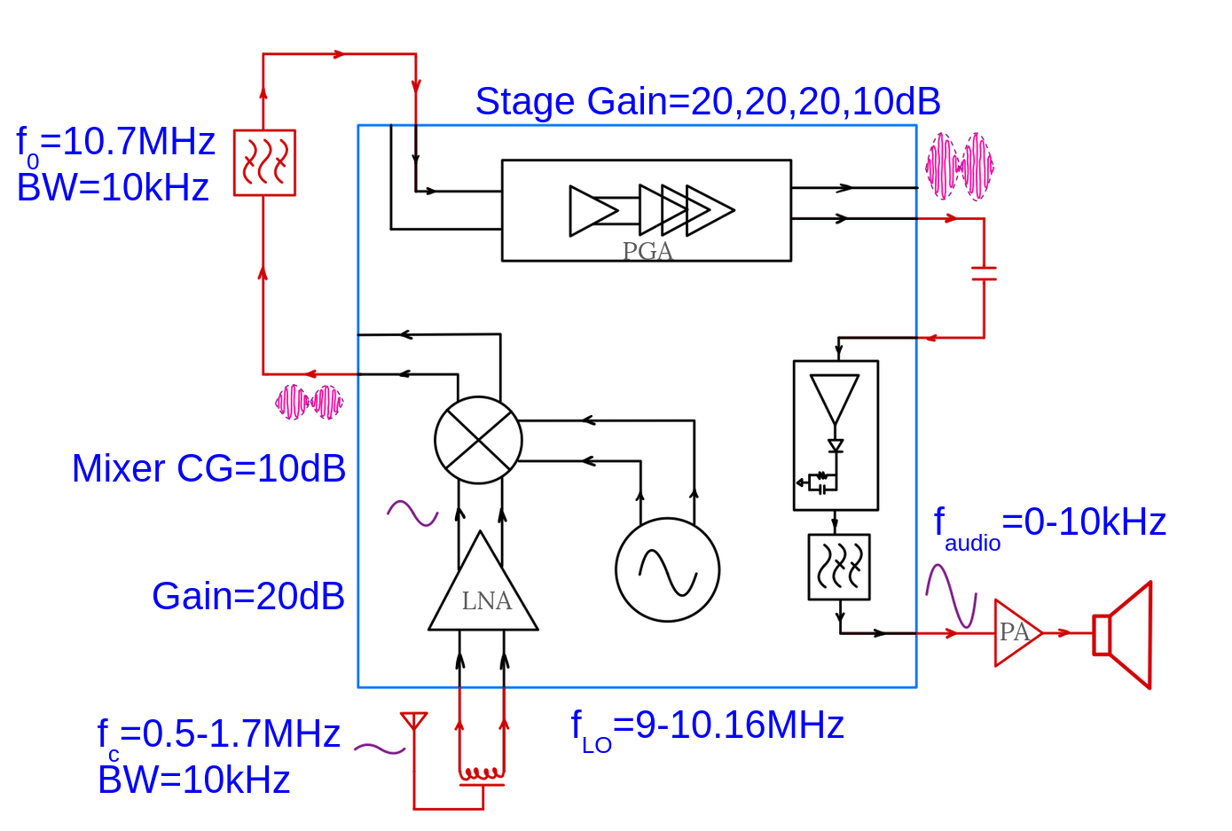
System block diagram
Why Upconversion:
In any superheterodyne system, there exists an unwanted signal that is spaced at a distance of twice the IF frequency in the direction of the LO relative to the desired carrier. Due to the low-frequency AM band, traditional down conversion results in image frequencies that occur in-band. To avoid the issue of in-band images, our system uses upconversion to 10.7 MHz, moving the image frequencies far outside the desired AM radio band. This architecture avoids the necessity of sharp roll-off, tunable, channel-select filters placed in front of the LNA, which can significantly degrade the SNR of the system.
Block Functionality:
The following is the description of the functionality of each block, through antenna input to the speaker output.
For offchip blocks: choose antenna and power amplifier from Elenco Inc. model AM-550CK dual audio superhet AM radio kit, and the crystal filter is ECS-10.7-15A from ECS Inc.
Antenna:
Use one coil on ferrite rod in parallel with a tunable capacitor as an antenna to receive the AM signals from the air. The tunable capacitor should be able to make the antenna resonate frequency from 540kHz to 1700kHz to capture and peak the target channel to the strongest signal level for better SNR.
Low Noise Amplifier(LNA):
As the first stage of the front end, an amplifier for frequency from 540kHz to 1700kHz with low noise design is required for better SNR.
Mixer:
In an AM receiver design, the mixer takes the amplified differential AM signal from the LNA (Low-Noise Amplifier) and the differential square wave generated by the LO (Local Oscillator). It combines these signals to produce an intermediate frequency (IF) signal of 10.7 MHz, which matches the natural frequency of the off-chip crystal filter.
Local Oscillator(LO):
As the system uses upconversion, LO works with Mixer to select the target channel, so the output frequency of the oscillator should be (10.7M-Target Station Central Frequency)Hz, which should cover 9MHz to 10.16MHz. Hence it should be a Voltage-Controlled Oscillator(VCO), and VCO output passes through the LO driver as the input of the Mixer.
Intermediate Frequency (IF) Bandpass Filter:
IF bandpass filters works to select the wanted channel from the Mixer output, which means it should have a passband of 10kHz, and offchip crystal filter ECS-10.7-15A with passband of 15kHz is the closet to demand.
Programmable Gain Amplifier(PGA):
Filtered IF signal goes into PGA and by changing the gain of the programmable gain amplifier to get the targeted output amplitude for demodulator. The first stage of PGA also designed to meet the filter's impedence matching requirement and do offset compensation offchip.
Demodulator:
The demodulator extracts the envelope from the 10.7 MHz modulated signal, where the envelope represents the audio signal. It also incorporates a second-order low-pass filter to eliminate high-frequency noise from the carrier signal, ensuring a clean audio output. The processed audio signal is then delivered to an off-chip power amplifier and speaker for playback.
Power Amplifier and Speaker:
The power amplifier boosts the weak audio signal from the demodulator to a level suitable for driving the speaker, ensuring efficient energy conversion and minimizing distortion. The amplified signal is then sent to the speaker, which converts it into sound waves through mechanical vibrations.