
Testing and Measurement
Signal Chain
Using the realistic sensor input the system can process the signal as designed. Different from the simulation ideal modulated sine signal the realistic input amplitude is not constant, it has the charge and discharge phase making the signal received more like a diamond shape instead of a square and high frequency noise from the ultrasonic receiver.
LPF of our system can keep the 40KHz ultrasonic signal with no attenuation and filter out the high-frequency signal from the sensor input.
The AC coupling method after PGA is causing some gain reduction due to the resistor value of the RC AC coupling.
The noise from the probe is about 2mV but the long-distance signal is approximately 10mV instead of the microvolts level we expected. In the laboratory environment, the design can measure a maximum distance of 2 meters.
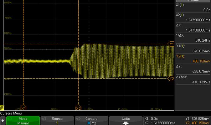
Figure 1: Amplification Stage
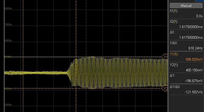
Figure 2: Filter Stage
Figure 2: Filter Stage
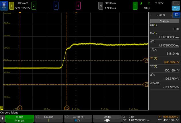
Figure 3: Envelope Stage
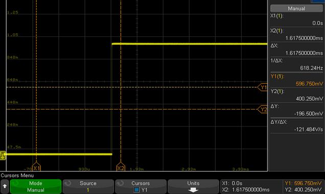
Figure 4: Comparator Stage
Distance Measurement
With our system set up, the distance measurement is a simple math equation of (delay between the supply and output signal rising edge in S) times 340m/s.
Measured 22cm
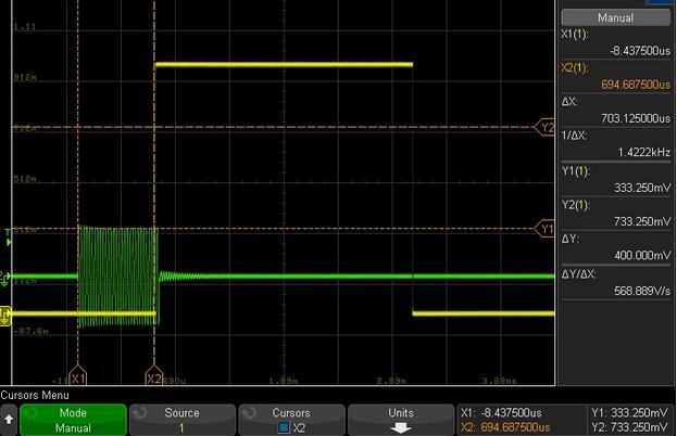
Figure 5: 703*10^-6 m x 340m/s = 21.09 cm
Measured 200cm
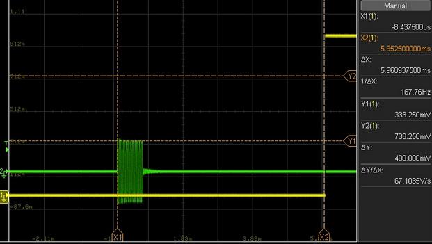
Figure 6: 5.96*10^-3 x 340 = 2.03m
With an Error less than 5%, the system needs to calibrate before the measurement. The accurate measurement range is from 10cm to 2 m.