
System and Signal Flow Overiew
The receiver detects the presence of a 40kHz signal and outputs a digital 1V signal with high/1V indicating the presence of a signal and low/0V indicating the absence of the 40kHz signal. The receiver chain has the necessary blocks for the signal conditioning and the detection of the envelope of a 40kHz signal.
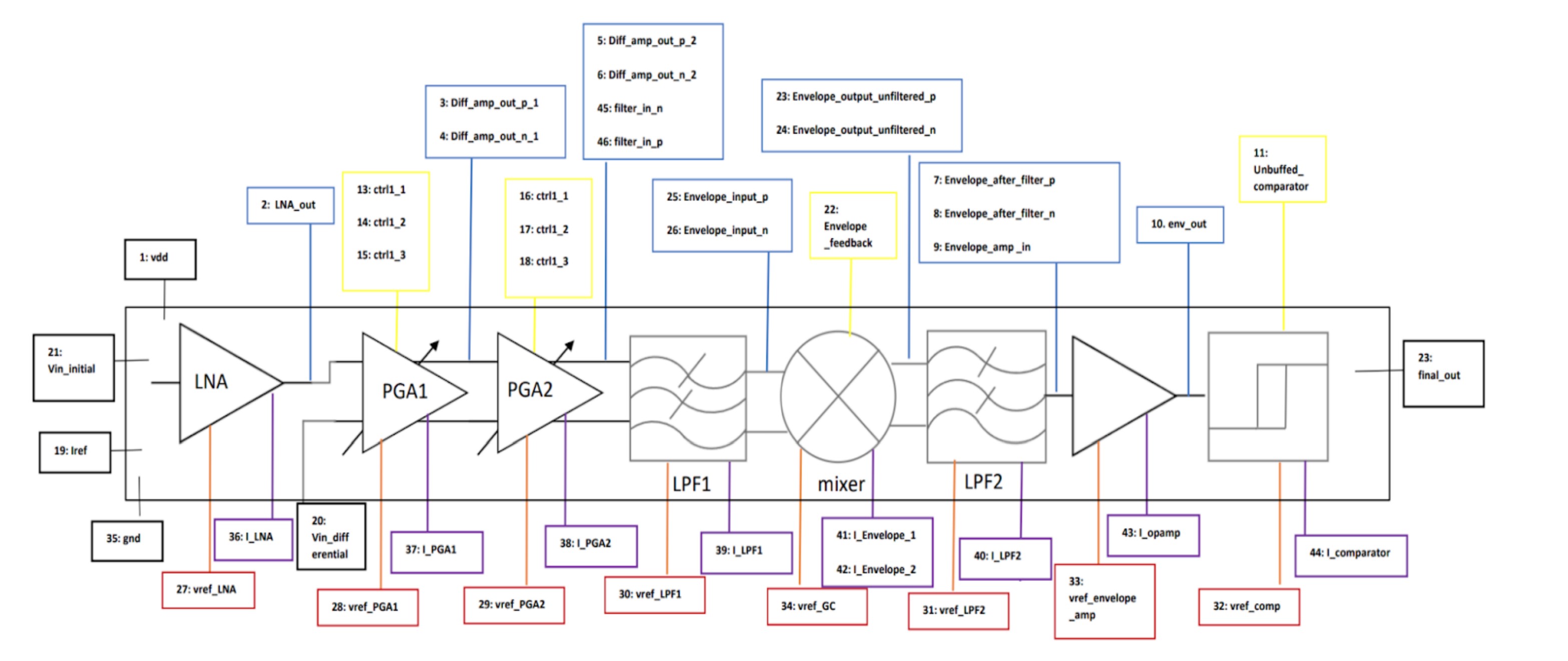
Figure 1: Chip block diagram
Amplification: The receiver front end starts with amplification stages. The first block is a single ended LNA (14dB, Signal ended OTA with resistive feedback) followed by differential 2 PGAs (0dB-20dB each, Differential OTAs with resistive feedback). The control over the PGA gain (By controlling the resistive feedback network) enables the detection of a wide range of input amplitudes. The low gain setting is to preserve linearity of the signal in presence of a large input signal (eg, short range object detection). The high gain settings are to accurately detect a smaller input signal (eg, long range object detection). The switch to differential signaling is to provide higher signal swing for the final comparator stage.
Filter stage 1 (Differential Tow-Thomas Biquad): A 2nd order lowpass filter (110kHz cutoff frequency) is used after the amplification stages to filter out high frequency noise. This is required before the self mixer's involvement, given its function, which transforms white noise into pink noise. This transformation yields a heightened DC output noise across all input noise frequencies. This manifests as noise in the envelope signal leading to false detections and misses at the comparator stage.
Mixer/Envelope Detector (Gilbert Cell): The Envelope Detector is a self mixer, which outputs a low frequency signal envelope, and a high frequency (80kHz) signal.
Filter stage 2 (Differential Tow-Thomas Biquad): This filter stage (10kHz cutoff frequency) is used to filter out the high frequency component of the mixer output (80kHz) while preserving the low frequency desired envelope (100Hz - 1kHz).
Additional Amplification: There is another amplifier stage with an off chip resistive feedback network. This is added to give some additional flexibility in controlling signal amplitude in the testing phase.
Comparator: This is the final stage of the receiver signal chain which digitizes the envelope signal at its input. The comparator has a minimum hysteresis of 15mV to make the output robust to glitches. It compares the input signal to a reference and gives a binary output to indicate the presence (High/ 1V) or absence (Low/ 0V) of the ultrasonic signal.
The waveforms below show the simulated signal waveform at each stage in the receiver system. System input (to the transducer), LNA input (output of transducer), Single ended LNA output, Differential PGA output, First filter stage output, Filtered Mixer/ Gilbert cell output (the envelope is visible), Additionally amplified output and finally the Digitized comparator output (Final system output).

Figure 2: Block Level Simulated Waveforms