System Overview
AM radio uses amplitude-modulation to transmit analog audio information over the air on medium wave (MW) carrier channel frequencies. The AM radio band spans from 540 kHz to 1700 kHz -- classified as medium wave (MW) radio. Within the allocated frequency band, AM broadcasting channels are spaced at carrier frequencies 10 kHz apart. The channels are divided into three categories based on their frequency, power, and active time of day: Clear, Regional and Local channels.
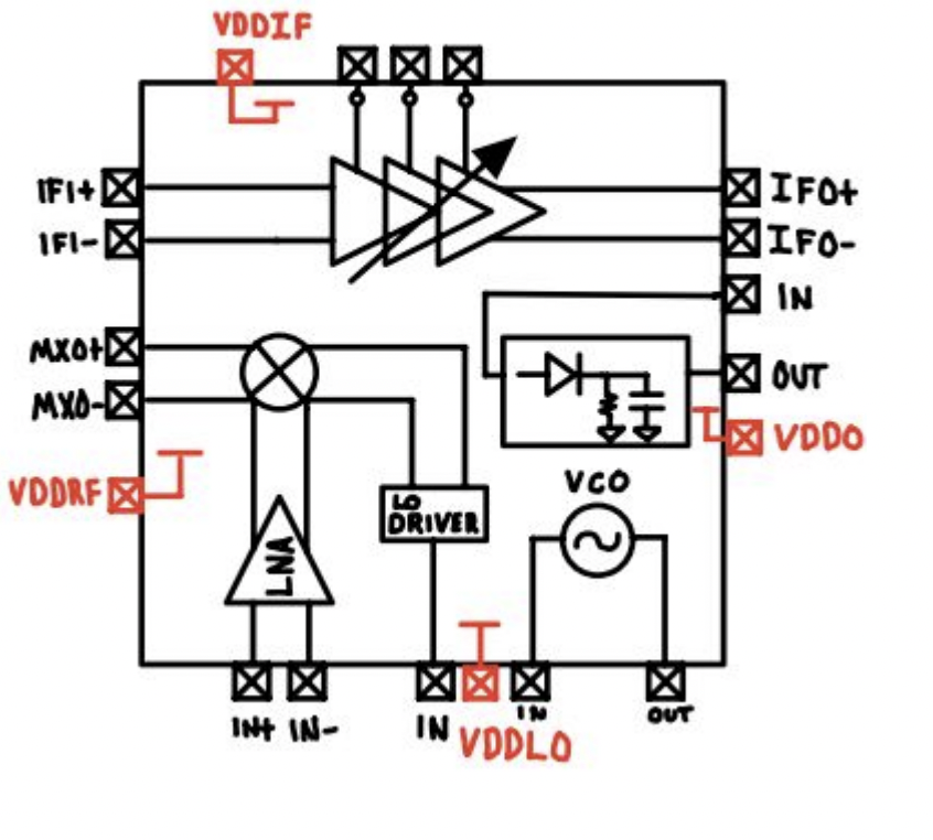
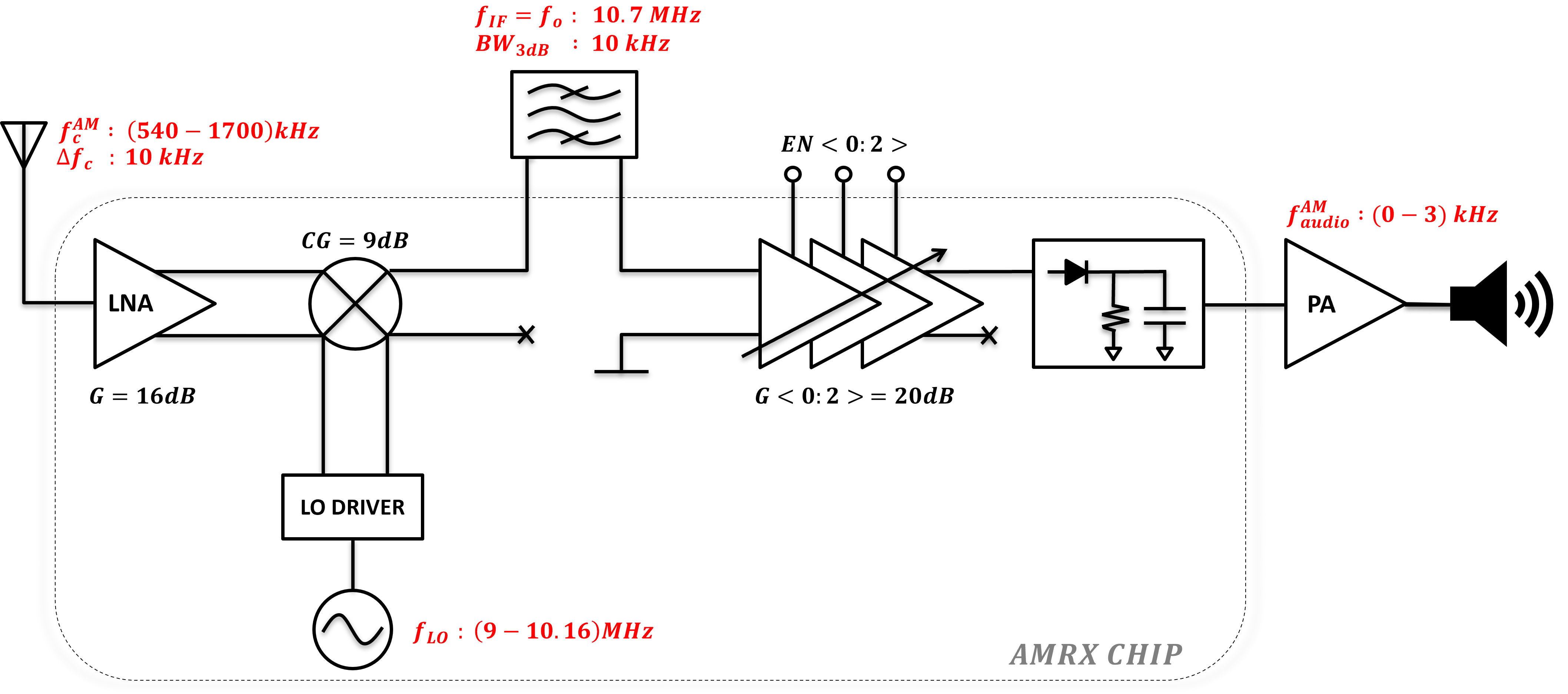
The front end is designed to process input signal levels ranging from 50uV to 5mV in order to accomodate the entire range of broadcast power. The system block diagram is shown in Figure 1 below. The carrier channels are received by a ferrite loop antenna coupled to the input of the LNA. Channel selection is accomplished by tuning the LO frequency such that the desired carrier is upconverted to a fixed intermediate-frequency (IF) of 10.7MHz. The upconverted carrier at the IF port is routed off chip to a crystal bandpass filter with a fixed center frequency of 10.7MHz. The filtered IF signal is then routed back on chip to the input of an IF programmable gain amplifier (IFPGA). The IFPGA gain is set by three control bits that together enable one of four possible gain settings: 1x, 10x, 100x, 1000x. The amplified AM signal at the output of the IFPGA is demodulated by a diode-based detector. The baseband audio signal is routed from the output of the detector to an external power amplifier (PA) capable of driving an 8&omega speaker.
UPCONVERSION FOR AM:
In any superheterodyne system there exists an unwanted signal that is spaced at a distance of twice the IF frequency, in the direction of the LO, relative to the desired carrier. Due to the low-frequency AM band, traditional down conversion results in image frequencies that occur in-band. To avoid the issue of in-band images, our system uses upconversion to 10.7 MHz, moving the image frequencies far outside the desired AM radio band. This architecture avoids the necessity of sharp roll-off, tunable, channel select filters placed infront of the LNA which can significantly degrade the SNR of the system.
BLOCK FUNCTIONALITY:
The following is a description of the functionality of each block in the receiver chain along the signal path as the signal flows from the antenna input to the speaker output.Antenna and Low Noise Amplifier (LNA):
The process begins with an antenna capturing the incoming AM signal spanning the frequency range of 540 kHz to 1700 kHz.
The received signal is then fed into a Low Noise Amplifier (LNA) designed to enhance the weak incoming signal while minimizing additional noise.
Mixer and Local Oscillator (LO):
Subsequently, the signal is directed to a mixer where it combines with a signal generated by a Voltage-Controlled Oscillator (VCO).
The VCO output, after passing through a Local Oscillator (LO) driver, provides a square wave LO signal that mixes with the incoming signal in the mixer.
Intermediate Frequency (IF) Bandpass Filter:
The mixed signal is then directed off-chip to an Intermediate Frequency (IF) Bandpass Filter (BPF) designed to isolate a specific frequency band centered at 10.7 MHz with a bandwidth of 10 kHz.
The filtered signal is then brought back onto the chip, ensuring that only the desired frequency components are retained.
Three-Stage IF Amplifier:
On the chip, the signal proceeds through a robust three-stage Immediate Frequency (IF) Amplifier.
The gain of each stage is individually controlled by three enable bits, providing flexibility in configuring the amplification levels.
On-Chip Detector:
The output of the IF Amplifier is then directed to an on-chip detector, responsible for demodulating the signal and extracting the amplitude modulation.
This demodulated signal represents the baseband audio signal.
AM Audio Processing and Power Amplification:
The demodulated AM audio signal, spanning the frequency range of 550 Hz to 3000 Hz, is then directed to a power amplifier.
The power amplifier enhances the strength of the audio signal to a level suitable for driving an external speaker.
Speaker Output:
Finally, the amplified audio signal is delivered to an external speaker, allowing the user to acoustically perceive the original modulated information captured by the antenna.
In essence, the AM Transceiver seamlessly integrates a series of specialized components, ranging from the initial signal capture through the antenna to the final audio output, offering a comprehensive solution for processing and demodulating AM signals. The dynamic control provided by the IF amplifier's enable bits ensures adaptability to varying signal strengths and environmental conditions. This system design reflects a balance of sensitivity, selectivity, and amplification to provide a reliable and efficient solution for AM signal reception and audio reproduction.