Testing
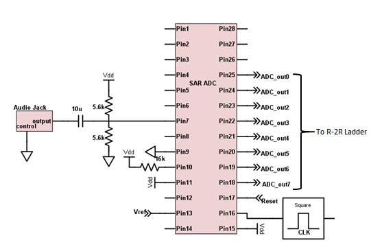
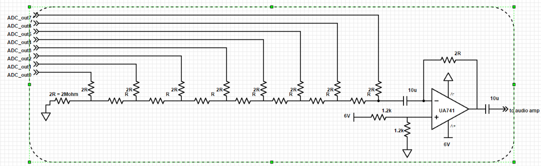
For the static testing, a demonstration was set up was made. An analog signals were to be provided to the input of ADC. Then the 8-bit output were input to self-created R-2R ladder based DAC, whose output was measured.
First a slow ramp input was given. To properly record enough data points, low frequency of 1 Khz with peak-to-peak voltage of 1V was provided to the ADC from the waveform generator as below:
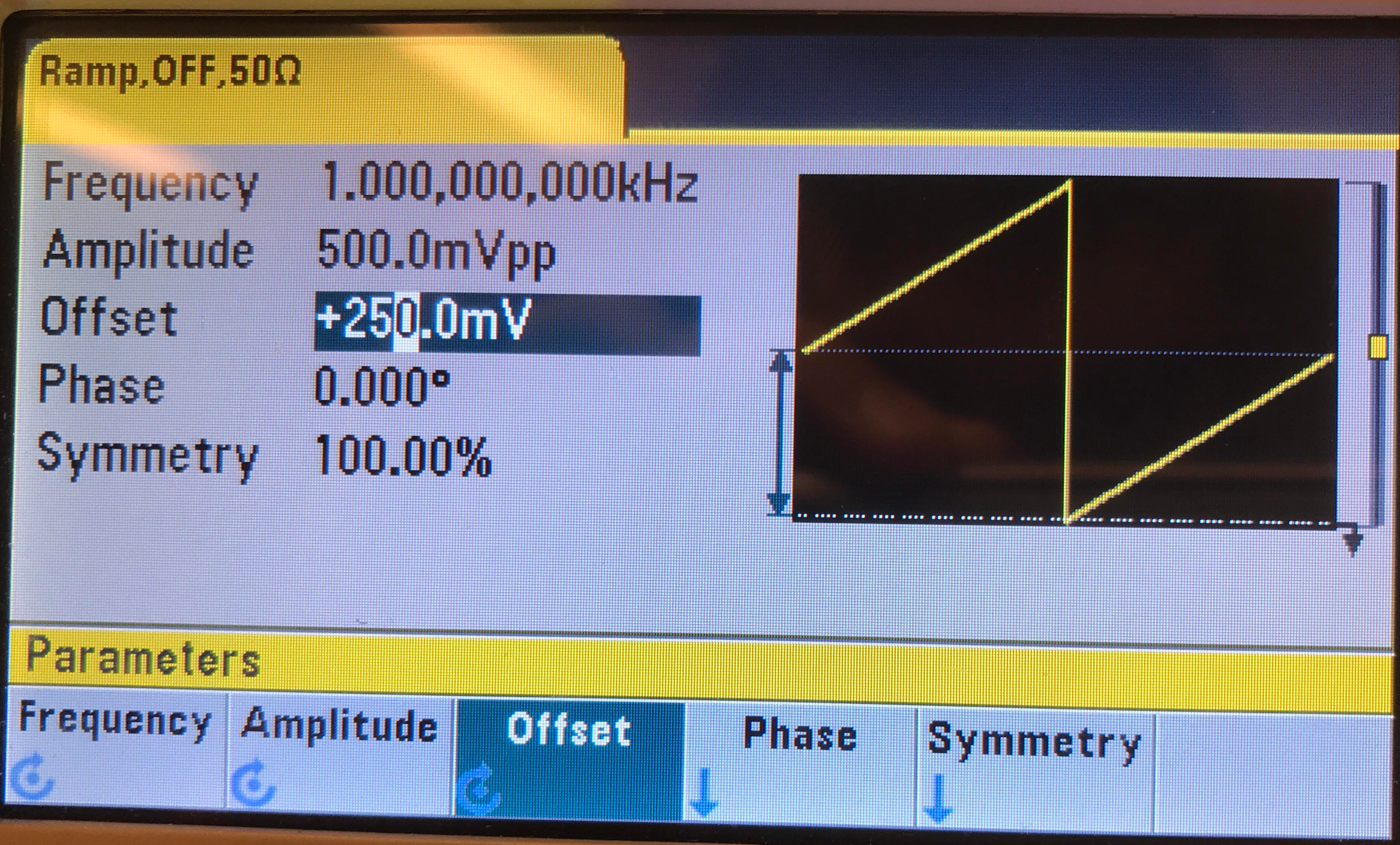
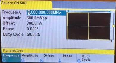
Then for the sampling, a 4MHz square wave clock was provided. This would be fast enough to sample few data points from every coded output. The waveform generator image is shown below:
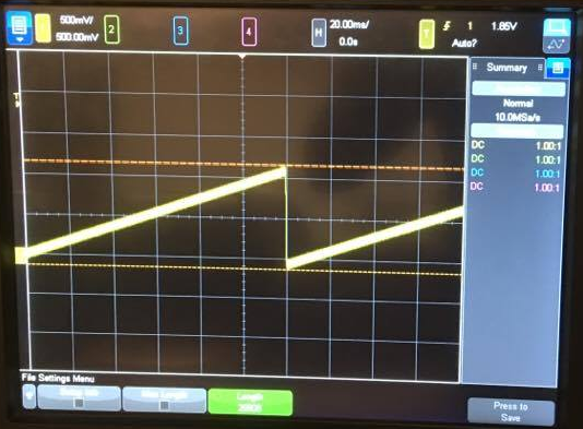
At the output, a clean ramp signal was observed as shown below. Looking closely at the output, a staircase response was observed. These data points were recoreded on the oscilloscope for further analysis.
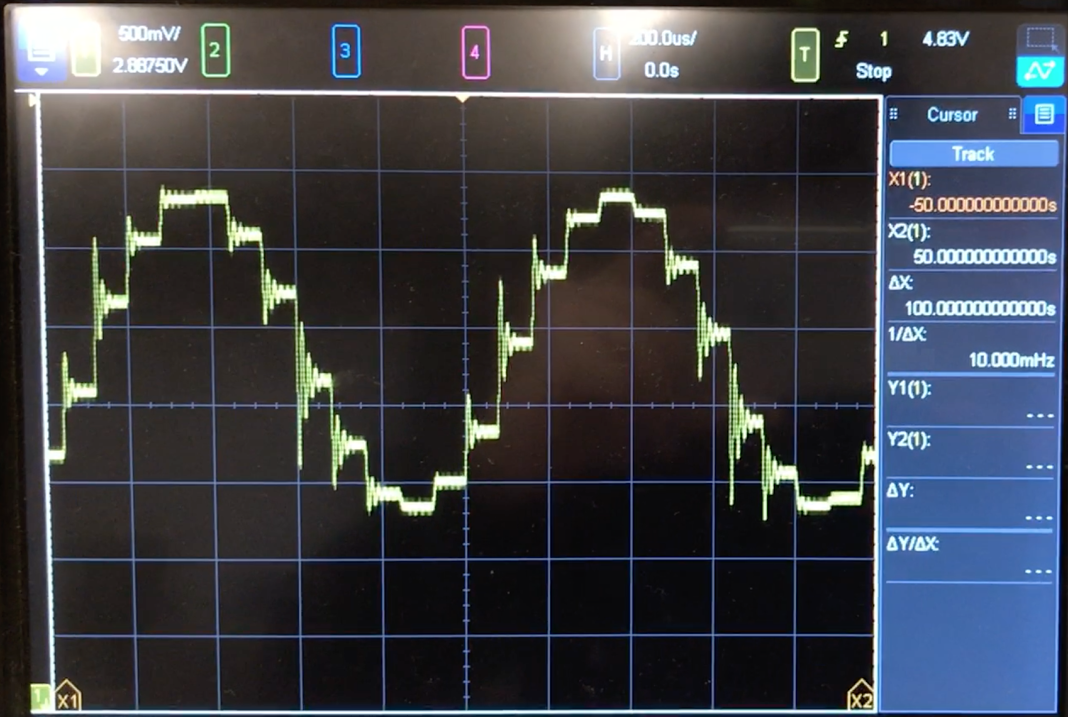
Similarly, for calculating SNR and SFDR along with the ENOB, 1Vpp, 1KHzsine wave input was given. There is a clear staircase response seen at the output. The ringing in the staircase is observed due to inaccuracy of precision resistors (+/- 5%).
Demonstration
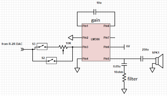
For practical demonstration, the input was provided as an audio from the laptop using the headphone jack and the output was played on the speaker. The output resembled the input with some noise.