
Testing
We started with power circuit tests, and then moved on to the input logic tests, crystal oscillator circuits tests, LED output driver tests, and in the end we plugged in the IC and run the integration test.
IC Bring-Up Tests
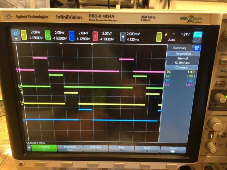
Before we have our PCBs manufactured, we powered up our ICs on a breadboard, using DC power supplies and probed the output pins on an oscilloscope. We measured the multiplexed enable outputs.
Power Circuit Tests
We started by providing a stable 9V power supply at the power plug, and we measured the voltage level at the output of first stage voltage regulator (5V). The second stage voltage regulator converts 5V power source to 1.8V as the VDD to the IC. We measured the VDD pin of the socket to ensure that the IC is powered at the appropriate voltage level.
Oscillator Circuit Tests
We have two on-board oscillation sources, one from the crystal resonance, and the other from an oscillator IC. Both of them generates a clock signal at 32,768 Hz. We measured their oscillation frequencies on an oscilloscope at the on-board test probe points.
LED Driver Tests
In order to tests LED driver before even plugging in the IC (to avoid the "magical smoke" at all costs), we set up the test environment to independently test the 7-segment display driver. We sweeped through all six enable signals and all seven segments to test every segment of each digit by pulling each pair of enable signals and segments to 1.8V from a DC source.
Integration Tests
With the confidence built up on all the peripharals' tests, we plugged in the IC to the socket and powered it up. You can find our working project at https://youtu.be/ruJ1Ey3eInc.