
PCB TESTING
For the PCB testing, we adjust the potentiometers to generate the bias current (100uA) and reference voltage(1.25V). We use Arduino to create control signals for LEDs and S/H. Then we use Arduino to capture the output square wave signal, AC, and DC signal at the same time and display the results on the oscilloscope.
PGA and Comparator Output
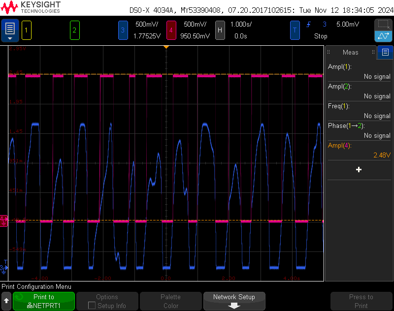
Fig 48. PGA and Comparator Output