Testing Result
The overall system can be seperated into 2.5V domain and 1V domain. 2.5 V domain is mainly for the PCB power supply, which also take the most part of power consumption. 1V domain is mainly for the chip, especially for digital core.
| Power Domain | Power Consupmtion (W) |
|---|---|
| 2.5V | ~300m |
| 1V | ~36u |
| Low-Power Mode | ~10m |
The time comparasion is done by comparing the current time from cell phone with our system.
| Accuracy |
|---|
| ~0.2s per hour |
Testing Signal Results
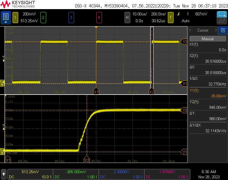
327hz_block1:
32768hz signal from XOUT
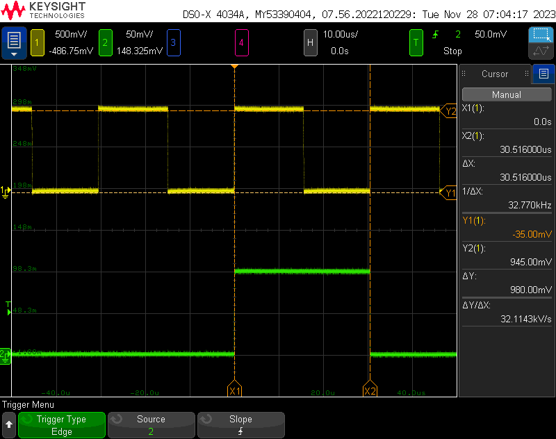
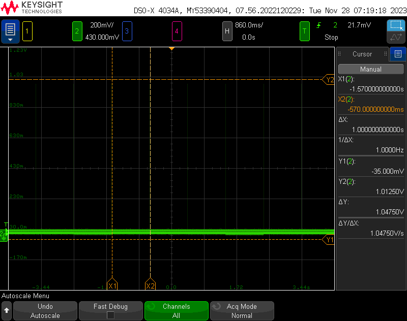
327hz with test1hz1:
32768hz signal from XOUT with testpin_1hz signal
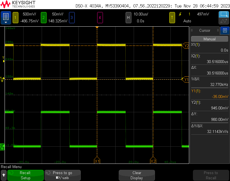
327hz with test32:
32768hz signal from XOUT with 32768hz from test32kpin
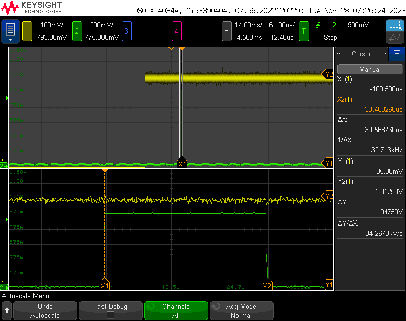
test1hz1:
1hz signal from test_1hzpin, each green pulse signal represent 1 s, the green pulse signal is not clear need to circuit
testb6-b6:
input signal of button 5 and correspondent testpin5 signal
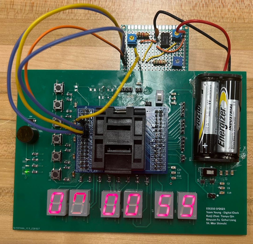
Clock under Testing
Figure 6 shows the clock in Clock Mode.
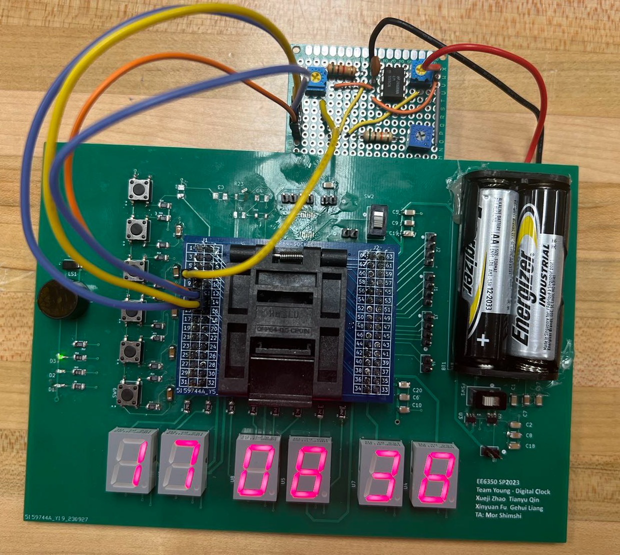
Figure 7 shows the clock in Date Mode.
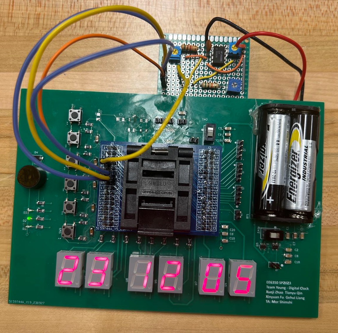
Figure 8 shows the clock in Timer Mode.