System Overview
Functionality Achievements
Three Main Modes
This chip is focus on realization of three-mode time display, 1. Clock, 2. Calendar, 3. Timer. Time display module on PCB board consists of 6 digits.
For clock mode, it adopts 24-hour format with HH:MM:SS, which counts from 00:00:00 to 23:59:59.
For calendar mode, the format is YY:MM:DD, which counts from Jan 01, XX00 to Dec 31, XX99. Especially, for canlendat mode, this chip takes the functionality of leap year into consideration. For example, in leap year, Februrary has 29 days while Februrary has only 28 days in other years. Also, beside leap year, this chip also considers the variation in the number of days in different months.
For timer mode, the time format is HH:MM:SS as well, which means it can counts down from 99:59:59 to 00:00:00. When it counts down to 00:00:00. The buzzer on PCB board will buzz. Any button except for "Reset" can be pressed to stop the alarm. Also, when the chip starts to count down, it is free to switch to other modes and will not be stuck at Timer mode.
Control Process and Time Adjustments
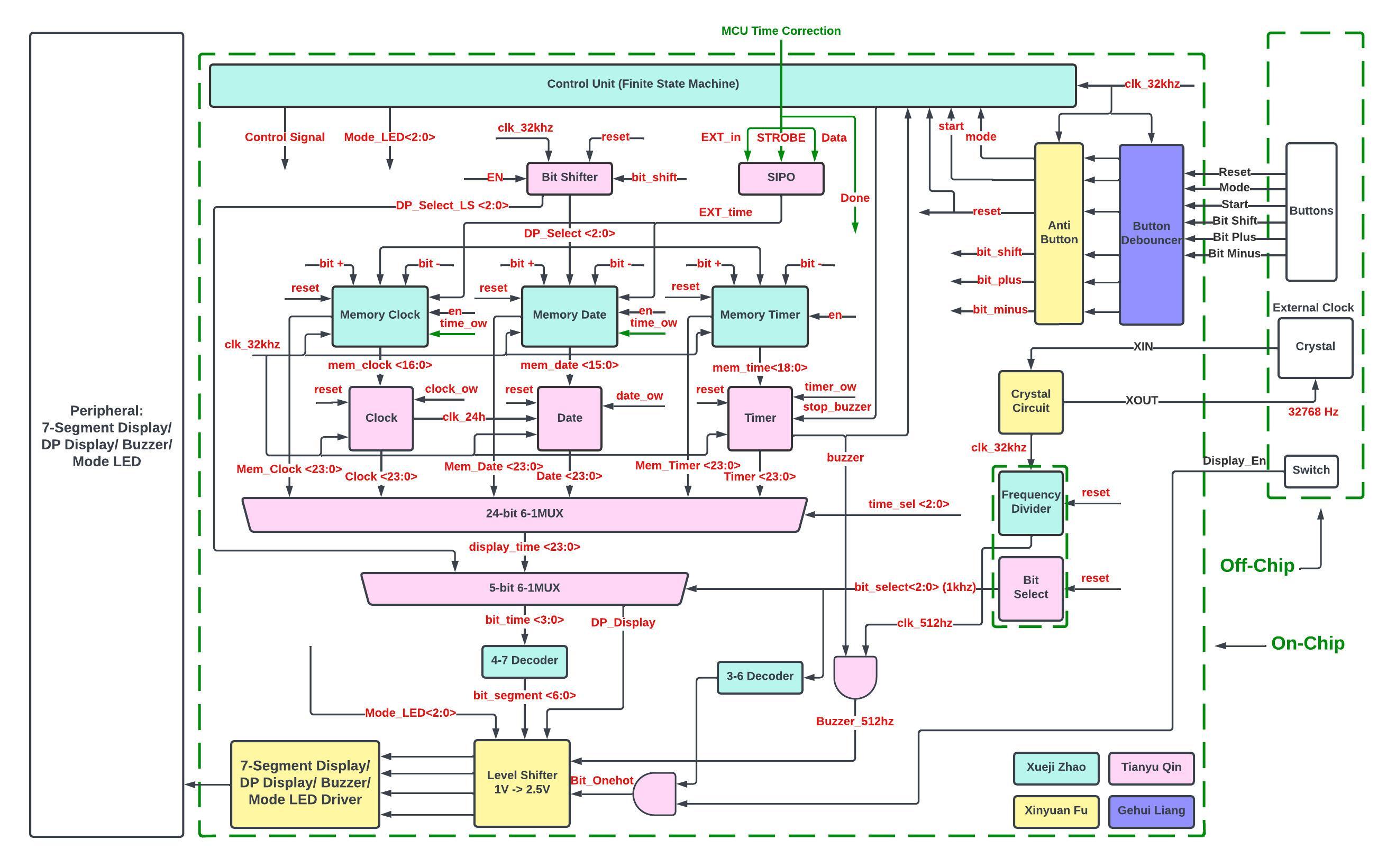
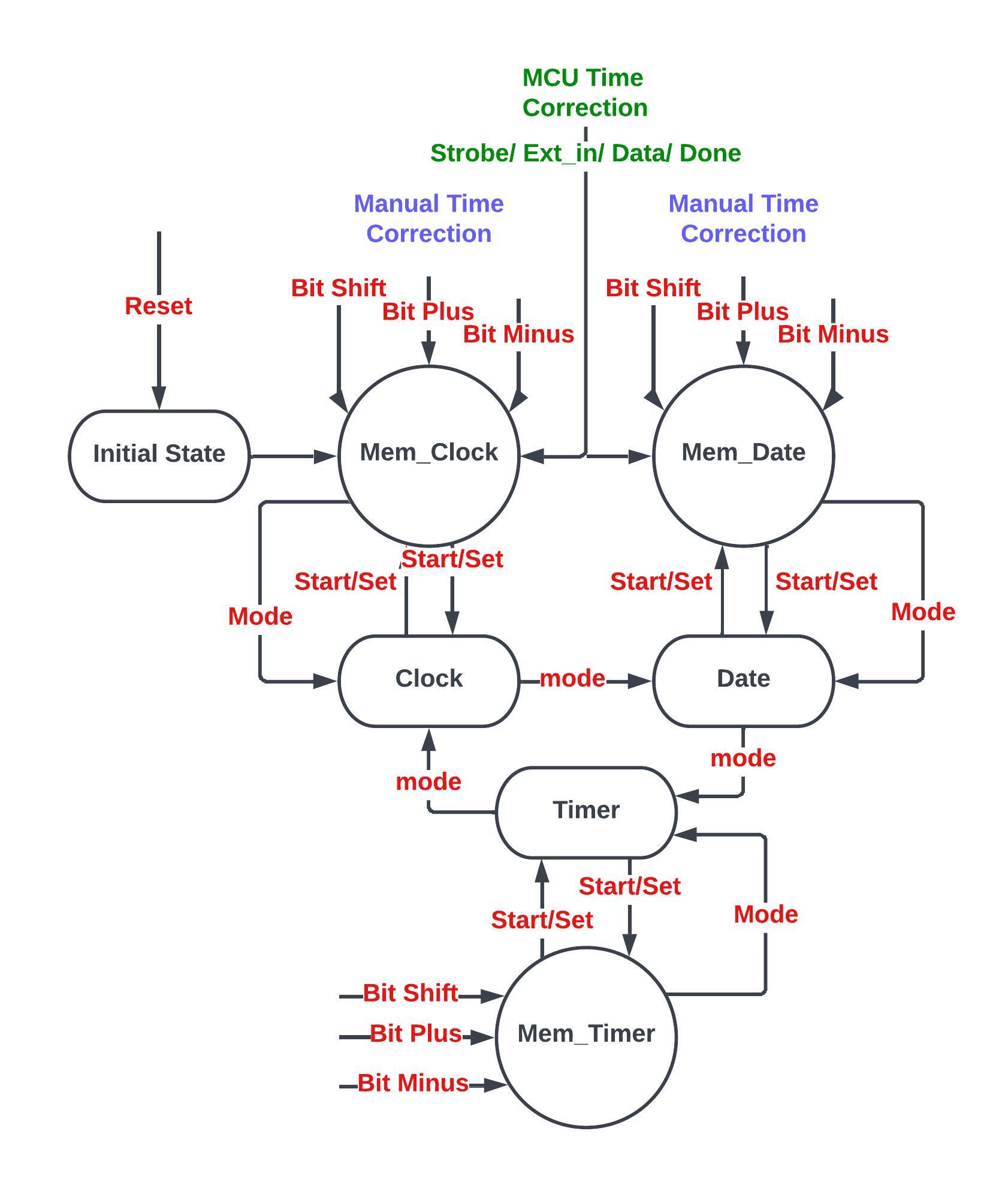
When it comes to control process, there has total 6 buttons in the design, Reset, Mode, Start/Set, Bit_Shift, Bit_Plus, Bit_Minus. "Reset" is a global synchronous reset signal. "Mode" signal is utilized to swith mode in Clock, Calendar, and Timer. "Start/Set" is a time setting signal. In one of these three mode as mentioned above, after pressing the "Start/Set", it will go to the corresponding "Mem_x" state which allows to use "Bit_Shift", "Bit_Plus", and "Bit_Minus" to do manual time adjustments. Then, "Start/Set" can be reused to setting the time or use "mode" to just switch back to previous mode without time adjustments.
Especially, besides the manual adjustments, for Clock and Calendar mode, a MCU interface is build up to adjust the time automatically. At that case, time data can be read from a MCU, like Arduino.
* Details of control process can also be checked in Fig 2. State Transitions.
Low Power Mode
After doing relative testing and simulation, Display Module on the PCB board takes up a great partial of power consumption. Thus, there has a special switch on PCB board to turn on the "Low Power Mode". At that mode, time and logic are stilling running. The only component shut down is the display module. Therefore, the power consumption is extremely decreased when the "Low Power Mode" is turnned on.* Brief Description can be found in Table 1. Main Functionalities.
| Functionalities | Description |
|---|---|
| Clock | Current time display(HH:MM:SS) |
| Calendar | Current date display(YY:MM:DD), leap year and variation of days are added |
| Timer | Timer(HH:MM:SS), buzz when countdown to 00:00:00 |
| Time Adjustments | 2 ways of time adjustments, 1. Mannual adjustment (Clock, Calendar, and Timer), 2. MCU automatic adjustment (Clock, and Calendar) |
| Low Power Mode | Turn off the display but keep the time counting |
Table 1. Main Functionalities