Testing

First, we tested the chip without the PCB on a breadboard. We used a power source, a frequency generator and probed the output pins to an oscilloscope. A complete testing report can be found here. Below we illustrate some main function outputs.

HTML5 Icon
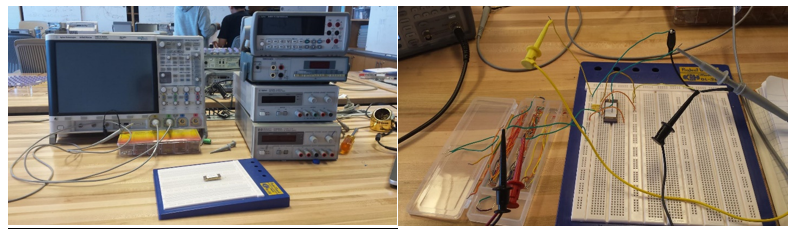
Fig. 35: Breadboard test


HTML5 Icon
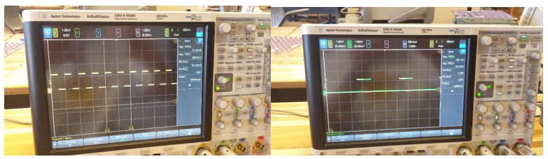
Fig. 36: 1Hz frequency & Enable Signals


HTML5 Icon
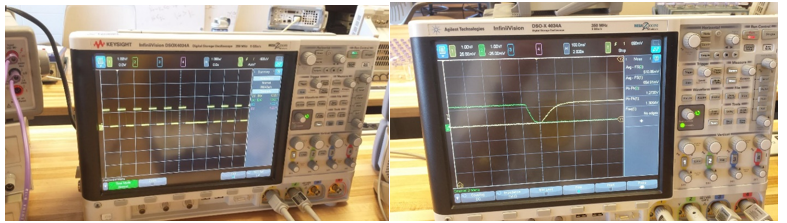
Fig. 37: Global Reset & Cross Enable verification


After verifying the chip's operation, we started testing it with the PCB.         Before plugging the chip, we measured the voltage at all crucial test-points like the regulator outputs. We did it first with the 9V battery source and then with the 5V USB.

HTML5 Icon
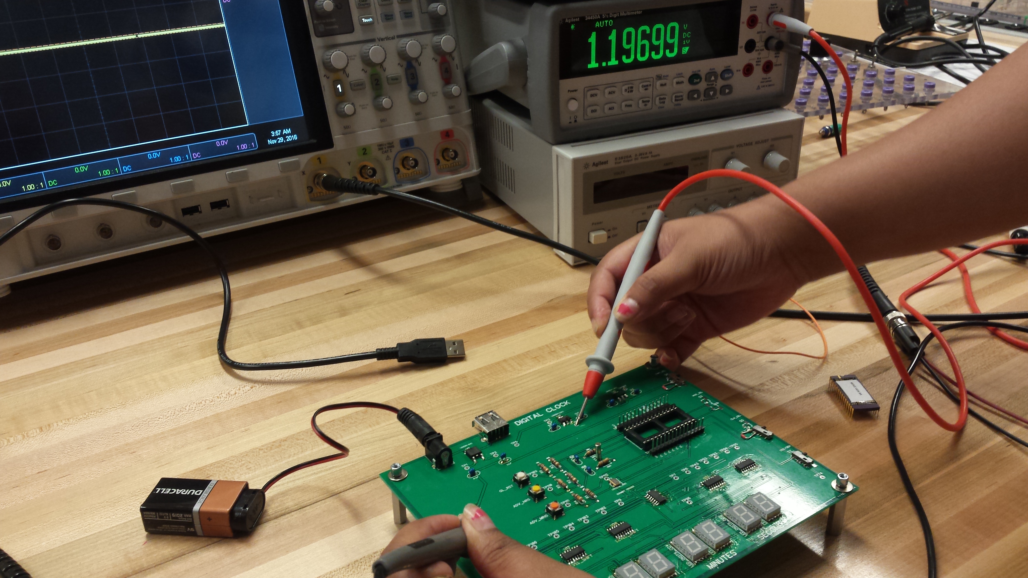
Fig. 38: Power Circuitry Test

        Next we tested the led displays by setting proper voltage values to the A-G segments and verifying the output of the LEDs.
        At this point we feel confident enough to place our chip on the PCB. Our first function test included the external frequency generator. By setting the appropriate values to our input pins, we could see the LED digits showing the proper output.
        Next we tested the crystal with the in-chip oscillator. Also we tested the external oscillator source as well.

HTML5 Icon
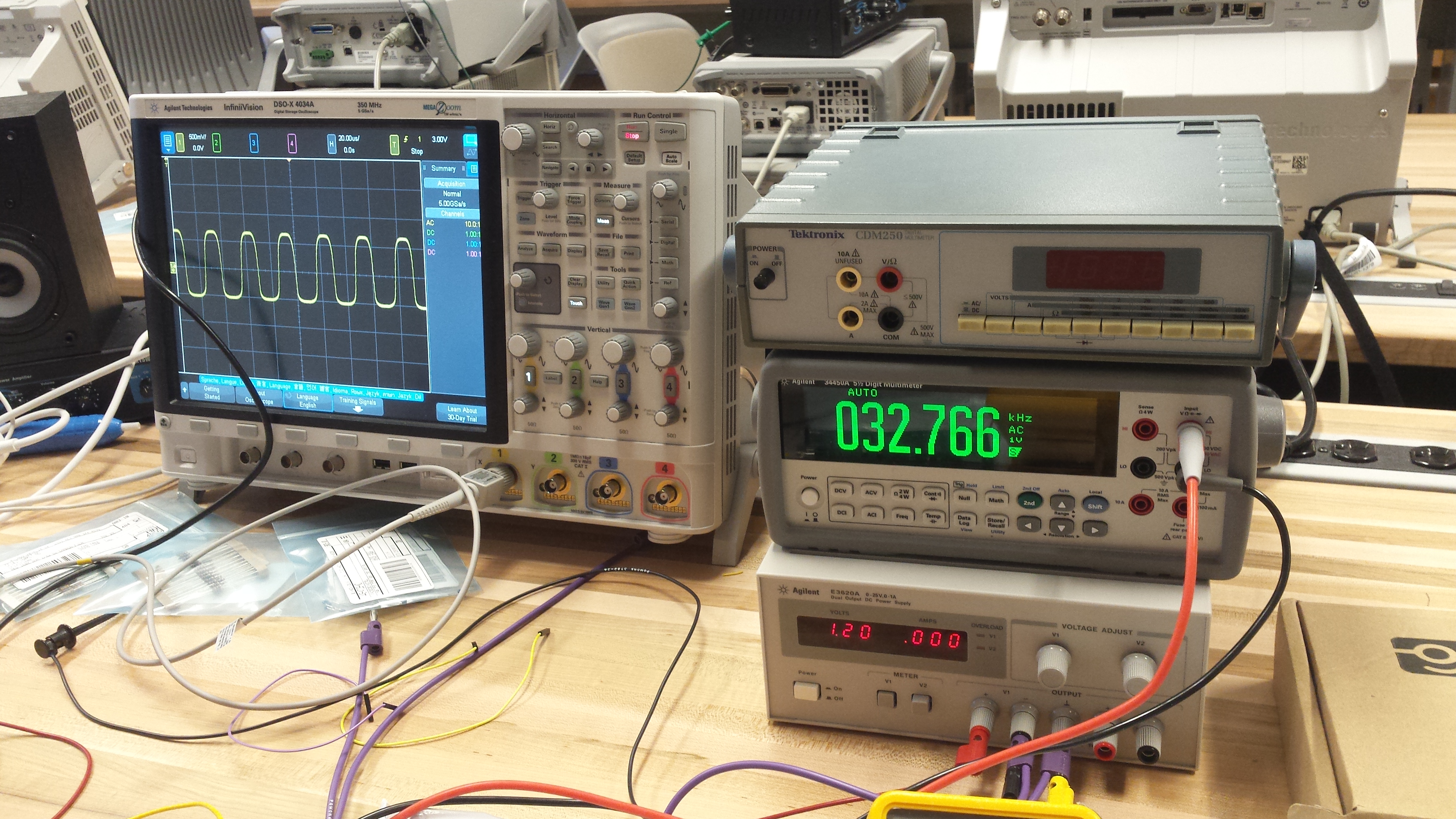
Fig. 39: Oscillator Output Frequency Test


HTML5 Icon
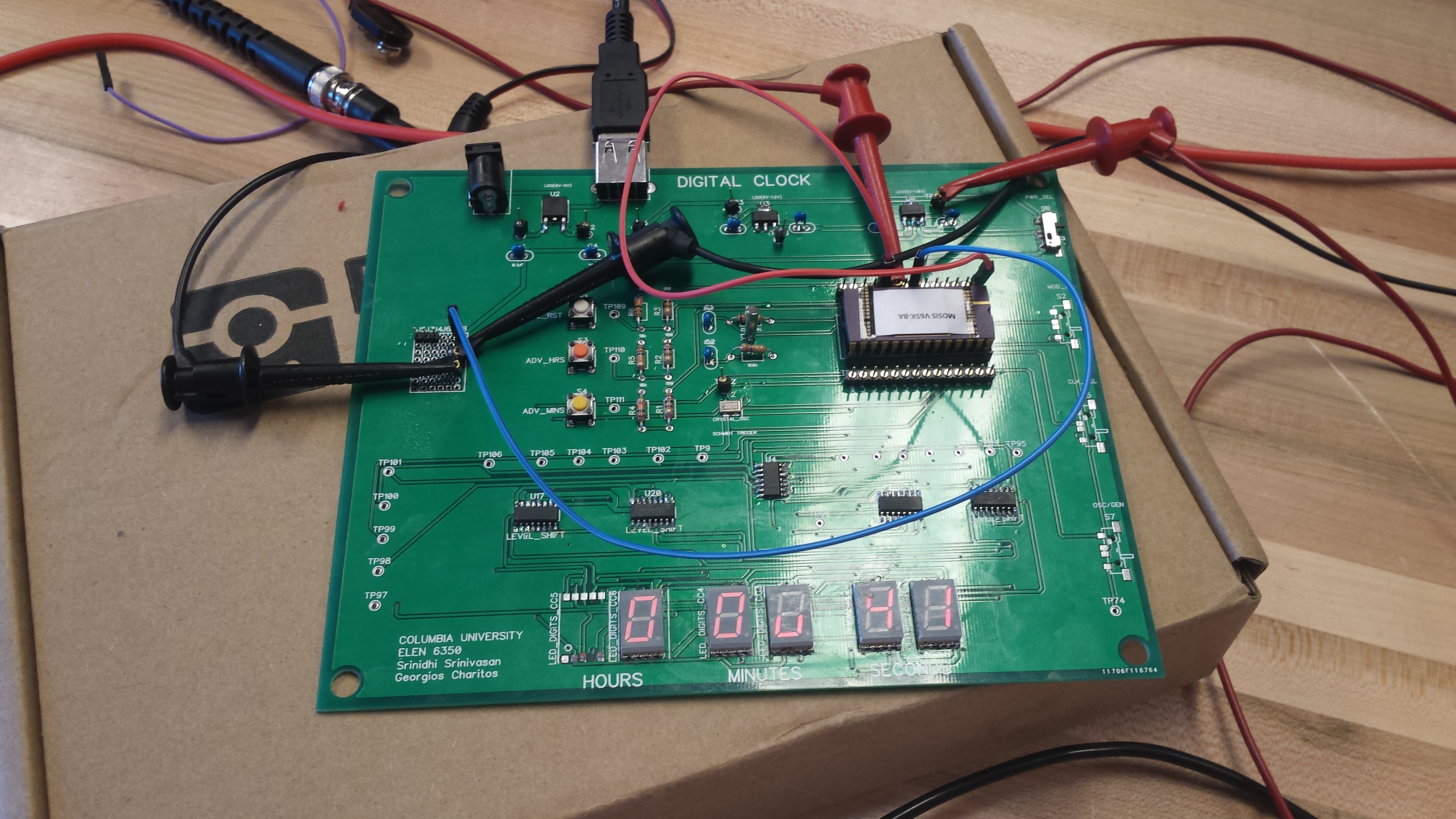
Fig. 40: Testing of PCB with chip mounted


Back to top