
Implementation Details
Topology used
The filter topology used was a cascade of Sallen-Key stages for immunity to component variations. Sallen-Key filters are susceptible to stability issues, when designed with a passband gain greater than unity, because of the presence of a positive feedback path. The stability is a concern, even for unity-gain stable amplifiers. Thus, component values had to be carefully chosen to ensure that the topology was sufficiently stable. Unfortunately, guaranteeing stability requires realization of the filter using large RC values. This was however, not a huge issue as the filter was designed to use off-chip resistors and capacitors.
Filter chain design
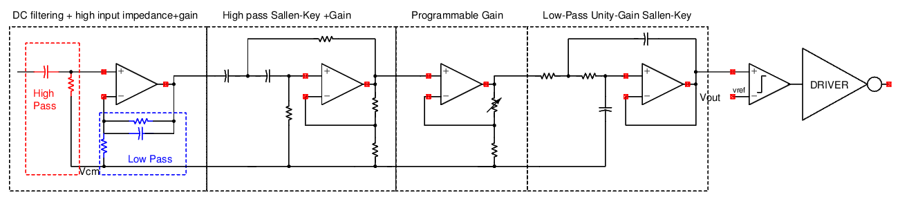
The heart-rate filter was designed to have a passband between 0.5 Hz and 3 Hz to capture heart rates between 30bpm and 200bpm (beats per minute). The respiratory rate filter was designed to have a passband between 0.05 Hz and 0.2Hz to capture respiratory rates between 3brpm and 12brpm (breaths per minute). The gain of both filter chains was tunable between 15 and 50, to ensure working across different users and different lighting conditions. The OTAs in the filter chain were all realized on the chip and the passive components required for transfer function realization were on-board.
Comparator design
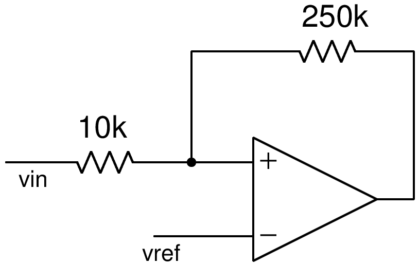
The comparator (FIG 2) was designed using an OTA configured as a Schmitt-Trigger by employing positive feedback. The resistances required for the positive feedback were realized on chip to ensure ratioed components. Good matching between the resistances is necessary for accurate realization of the voltage Hysterisis.
OTA design

The Operational transconductance amplifier was designed as a two stage miller compensated OTA with a zero-cancelling resistor. The MOSFETs used were ratioed so as to minimize systematic offset. The input bias current to the OTA is $4\mu A$ and the total OTA current consumption was close to $32\mu A$. The unity gain bandwidth of the OTA is 2MHz which was deemed sufficient for the purposes of the filters designed and the Open loop gain is ~70dB. An OTA was designed instead of an Operational amplifier, with the knowledge that the loads driven would not be heavier than the load presented by the intrinsic output impedence of the OTA itself.
Sallen-Key Stability analysis
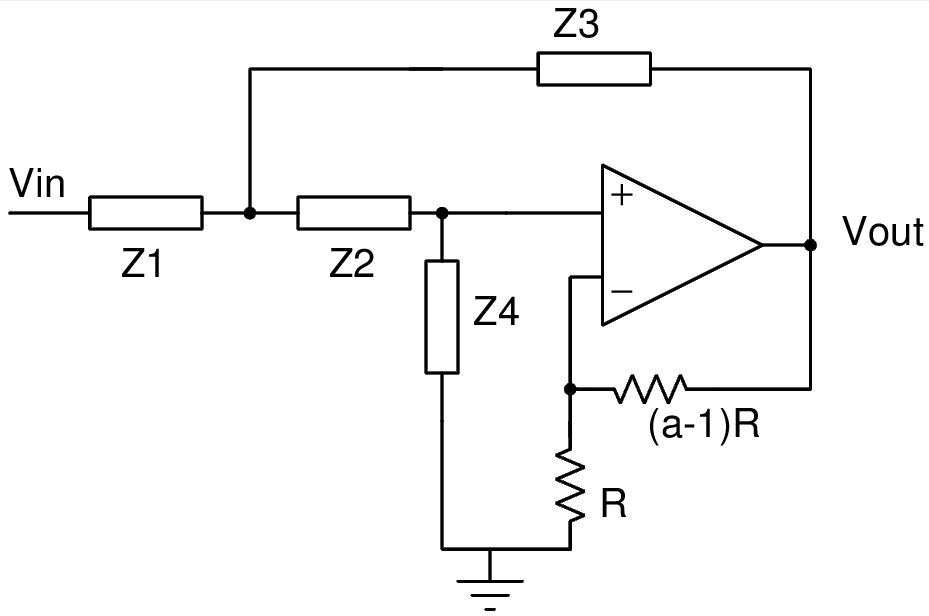
The generalized Sallen-Key filter (FIG 4) has an input to output transfer function (assuming an ideal Opamp) given by -
\[\dfrac{V_{out}}{V_{in}}=\dfrac{a\times Z_{3}Z_{4}}{Z_{1}Z_{3}+Z_{1}Z_{2}+Z_{2}Z_{3}+Z_{3}Z_{4}+(1-a)\times Z_{1}Z_{4}}\]In the highpass case, when $Z_{1}=\dfrac{1}{sC_{1}}$, $Z_{2}=\dfrac{1}{sC_{2}}$, $Z_{3}=R_{1}$ and $Z_{4}=R_{2}$, the expression reduces to -
\[\dfrac{V_{out}}{V_{in}}=\dfrac{a\times s^{2}C_{1}C_{2}R_{1}R_{2}}{1+s(R_{1}(C_{1}+C_{2})+(1-a)C_{2}R_{2})+s^{2}C_{1}C_{2}R_{1}R_{2}}\].It is obvious, looking at the characteristic polynomial that for the poles to lie in the left half plane, we require that, $a<1+\dfrac{R_{1}}{R_{2}}\times \bigg(1+\dfrac{C_{1}}{C_{2}}\bigg)$. Thus, increasing the gain while maintaining a reasonable quality factor, requires the ratio of $R_{1}$ to $R_{2}$ and $C_{1}$ to $C_{2}$ to be increased.
A similar stability analysis can be applied to Low-Pass Sallen-Key filters. In this design, however, the low-pass Sallen-Key structure was configured in unity gain feedback, which is unconditionally stable for ideal opamps. The intrinsic poles of the OTA itself, are at a much higher frequency than the passband region of the filter. Hence, the loop for all practical purposes has a dominant pole determined by the passive components that determine filter characteristics and the impact of the intrinsic poles of the opamps, themselves can be conveniently ignored.