System Overview
Audio amplifier is used to amplify the low power audio signals to the level that is suitable for driving loudspeakers. In nowadays mobile design, the power efficiency is top priority among all the design metrics. Class-D amplifier utilize the transistors as switches, which increases the efficiency dramatically. Although the switching activity introduces distortion into the system, it can be reduced significantly using feedback technique. The topology we chose, which is known as Bridged-Tied Load (BTL) class D amplifier, can produce 4x larger output power compared to then signal-ended topology. Figure 1 shows the system block diagram of our class D amplifier.
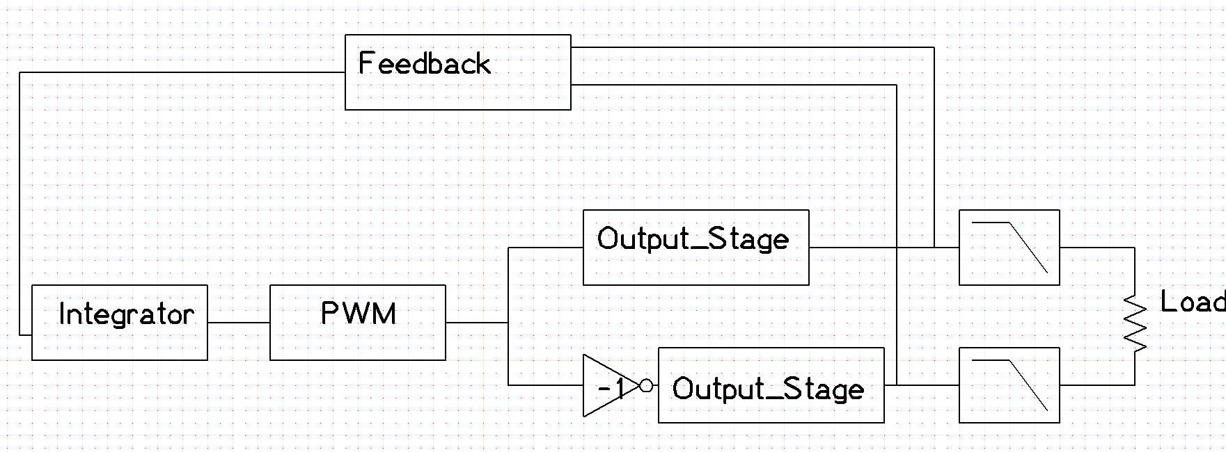
The audio input to the system flows into the integrator and then enters the PWM block to generate PWM control signal. There are two control signals which are 180$^{\circ}$ out of phase from each other. They are used to control the two output stage respectively to generate the differential version of signals to drive the full bridged load. External low pass filter are used to reproduce the input signal. The two differential signals are also converted to single-ended signal by the feedback adder and then feedback to the input to further decrease the distortion of the system.
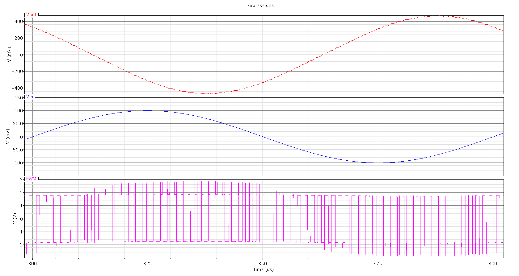
Figure 2 shows the input and differential PWM output and output signal after filter of BTL class-D amplifier topology. If there is no input, the output PWM should have a duty cycle of 50% and match each other. So the differential output becomes 0. Once the amplitude goes to positive, the duty cycle of the in phase signal decreases and duty cycle of the out phase signal increases, so the differential PWM output has negative amplitude.