
PCB Design
A custom PCB was designed to connect the JSQX6350 chip with peripheral circuits, sensor, microcontroller and the LCD display. We used Arduino Uno as the microcontroller to compute the heart beats rate and drive the LCD display, and the physical connection was made using compatible pin headers to avoid wires. Similiar connection was made for LCD display. The schematics and layout were designed using the PCB Artist. The schematic on the figure 13 shows only the essential components and connections to use the PPG6350. For the detailed PCB schematic and layout design, please refer to the files. The power supply for Arudino was a 9V battery. The 1.8V power supply for the chip was generated by feeding a regulator with 9V supply. The 5V power supply for the LCD was provided directly by the Arduino and is also used to supply the sensor. Meanwhile, the 5V supply of Arduino is also feed into a 0.9V regulator to get the reference voltage.
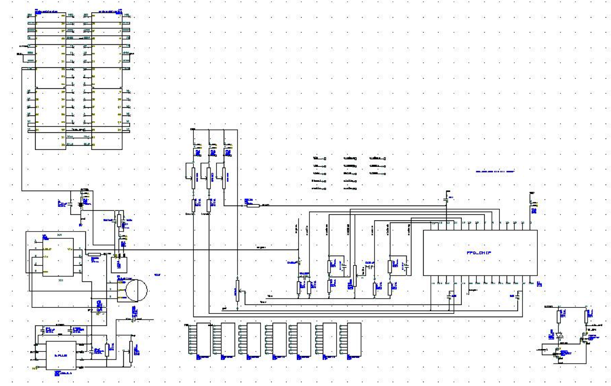
PCB Schematic
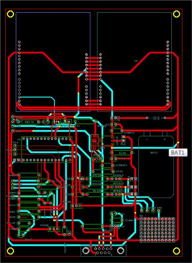
PCB Layout
 Download PCB Schematic
Download PCB Layout
Download PCB Schematic
Download PCB Layout
Arduino Source Code
For this system, we have 3 monitoring mode which is selected by 4 push buttons. When mode 1 is selected, the heart beats rate information updates for every beats, based on the time interval between 2 consecutive beats. For mode 2, bpm information is only updates when the fluctuation is more than 2 bpm, which will monitoring major fluctuation of heart beats rate changes will remain a stead counts. For mode 3, the heart beat rate information will updates every 5 seconds. And one additional push buttons is used to reset the system.
Download Arduino Source Code
		#include <LCD16x2.h>
		#include <Wire.h>

		LCD16x2 lcd;
		const int  inputPin = 2;
		int inputstate = HIGH;
		int lastinputstate = HIGH;
		int buttons;
		int button_state = 0;
		unsigned long previousTime = 0;
		unsigned long time_begin = 0;
		int interv=5000;
		float bpm = 0.0;
		float bpm_old = 0.0;


		void setup(){
		  Wire.begin();
		  Serial.begin(9600);

		  pinMode(inputPin, INPUT);

		  lcd.lcdClear();

		  lcd.lcdGoToXY(1,1);
		  lcd.lcdWrite("Welcome!");

		  lcd.lcdGoToXY(10,1);
		  lcd.lcdWrite("MODE:");

		  lcd.lcdGoToXY(1,2);
		  lcd.lcdWrite("HBR is:");

		  lcd.lcdGoToXY(14,2);
		  lcd.lcdWrite("bpm");
		}
		void loop(){

		  buttons = lcd.readButtons();
		  if (buttons == 14) // button 1 pushed, update each beats
		    button_state = 14;
		  else if (buttons == 13) // button 2 pushed, update when bpm fluctuate more than 2
		    button_state = 13;
		  else if (buttons == 11) // button 3 pushed, updates every 5 sec
		    button_state = 11;
		  else if (buttons == 7) // button 4 pushed, reset
		    button_state = 7;

		  inputstate = digitalRead(inputPin);

		  if (inputstate != lastinputstate) {
		    // if the state has changed
		    if (inputstate == LOW) { // falling edge
		      unsigned long currentTime = millis();
		      unsigned long time_diff = currentTime - previousTime;
		      previousTime = currentTime;
		      bpm =  60000.0/ time_diff;
		      lcd.lcdGoToXY(16,1);
		      if (button_state == 14)
		       {
		          lcd.lcdWrite("1");
		          lcd.lcdGoToXY(8,2);
		          if (bpm_old != bpm )
		            {
		              bpm_old = bpm;
		              lcd.lcdWrite(bpm,2);
		            }

		       }
		      else if (button_state == 7)
		       {
		          lcd.lcdWrite("0");
		          lcd.lcdGoToXY(8,2);
		          lcd.lcdWrite("      ");
		       }
		      else if (button_state == 13)
		        {
		          lcd.lcdWrite("2");
		          lcd.lcdGoToXY(8,2);
		          if (bpm_old - bpm > 2 || bpm_old - bpm < -2)
		            {
		              lcd.lcdWrite(bpm,2);
		              bpm_old = bpm;
		            }
		        }
		      else if (button_state == 11)
		        {
		          lcd.lcdWrite("3");
		          unsigned long time_last=0;
		          time_begin = millis();
		          int button_p = 11;
		          int count=0;
		          while((millis()-time_begin) < interv)
		          {
		            buttons = lcd.readButtons();
		            if (buttons == 14)
		            {
		              button_state = 14;
		              break;
		            }
		            else if (buttons == 13)
		            {
		              button_state = 13;
		              break;
		            }
		            else if (buttons == 7)
		            {
		              button_state = 7;
		              break;
		            }

		            inputstate = digitalRead(inputPin);

		            if (inputstate != lastinputstate) {
		              // if the state has changed
		              if (inputstate == LOW) { // falling edge
		                  count++;
		                  time_last = millis();
		                  button_p = 7;
		                }
		                lastinputstate = inputstate;
		              }


		             delay(50);
		          }

		          time_last = time_last - time_begin;
		          bpm = count * 60 / (time_last/ 1000.0);
		          lcd.lcdGoToXY(8,2);
		          if (bpm_old != bpm )
		            {
		              lcd.lcdWrite("      ");
		              bpm_old = bpm;
		            }
		          lcd.lcdWrite(bpm,2);
		        }
		      else
		        {
		          lcd.lcdWrite("0");
		        }

		    }
		   lastinputstate = inputstate;
		  }

		  delay(50);
		}