PCB Design
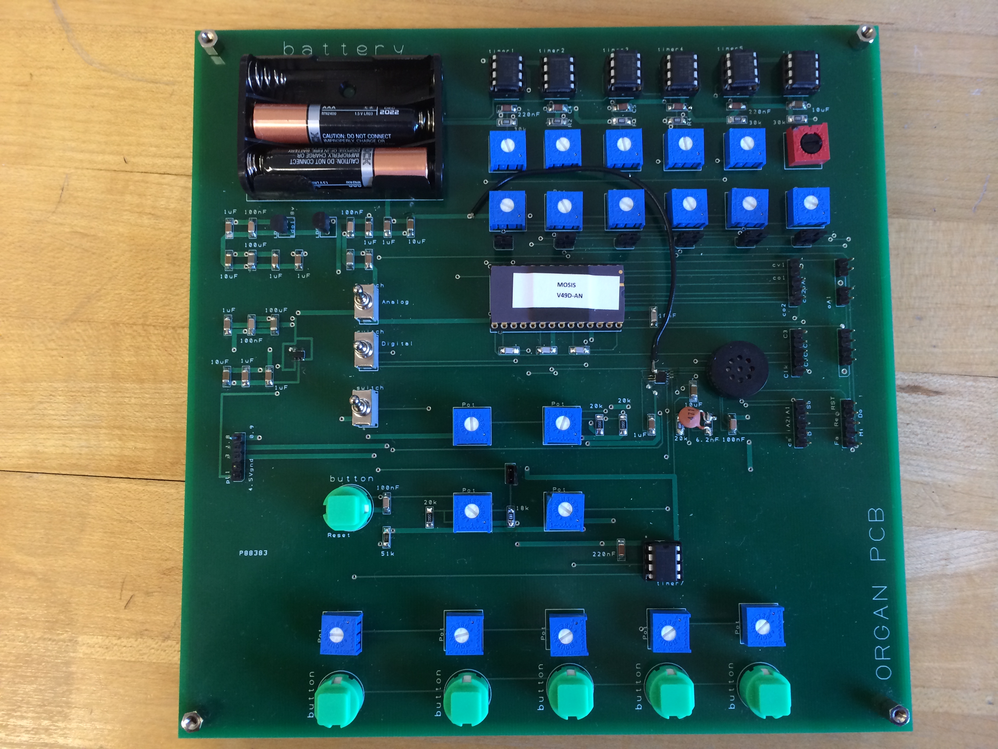
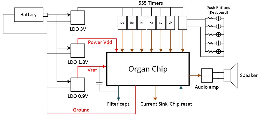
To test the functionality of the chip, a custom PCB was designed using the software PCB Artist, the schematic on the figure shows the abstract layout for the PCB. There are three voltage regulators to generate the supply voltage with the 4.5V supplied by the batteries, the 1.8V power supply for the chip, the 3V power supply to 555 timers, and the 0.9V reference voltage. Also, the 555 timers in the design is used to generate the different input frequency from Middle C to Middle G, and the digital clock frequency. For the electronic organ part, we use push buttons as the keyboard to select different resistor value for 555 timer to generate the corresponding frequency.