
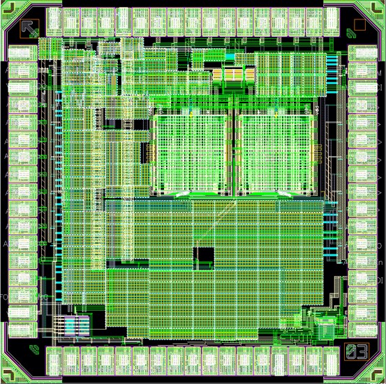
IC Layout
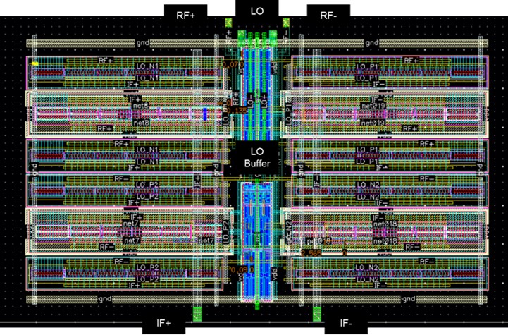
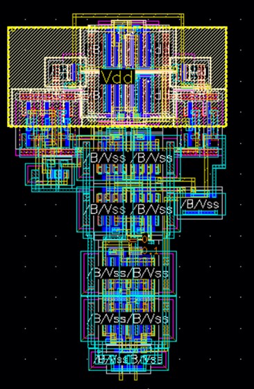
Mixer
The layout of the mixer is made centroid and interdigitated to reduce the effect of process variability. This ensured the reduction of offsets and even order distortions. The LO signals going into the mixer are buffered using FO4 to ensure fast rise times and turn on of the MOSFETs.
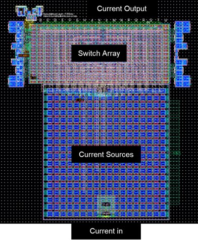
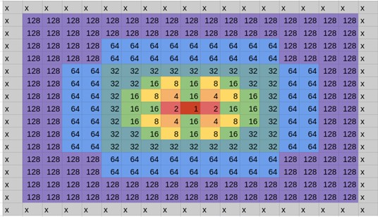
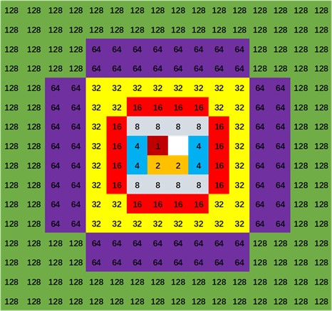
8-bit Current-Steering DAC
The selection of the current source and switch array structure as well as their layout presents a challenge in the DAC design. Components values are scaled from a size of A (unit size), then 2*A, 4*A, 8*A, 16*A, 32*A, 64*A, and ultimately 128*A. The elements are arranged using the common centroid matching method.
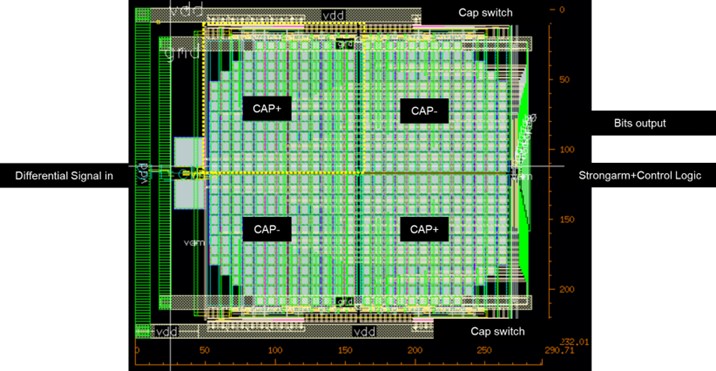
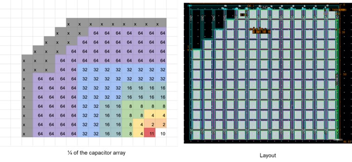
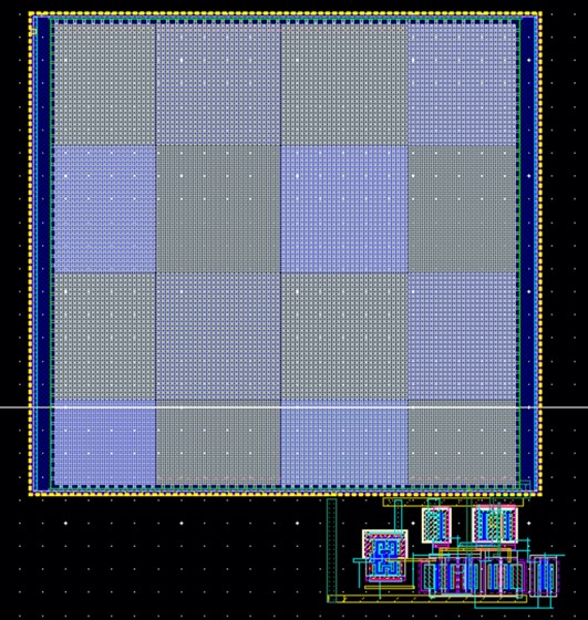
8-bit SAR ADC
Common centroid matching is also used in the layout of the ADC's capacitor array.
Zero-Crossing Counter
.jpg)