
IC Layout
Figure 13 shows the top-level layout of our IC. We use three pins for power and three pins for ground. Each OTA and the comparator have their own current source, set by a resistor in series with each module’s biasing portion, so three pins are used here. Decoupling capacitors composed to transistors are placed between power and ground to stabilize the power supply.
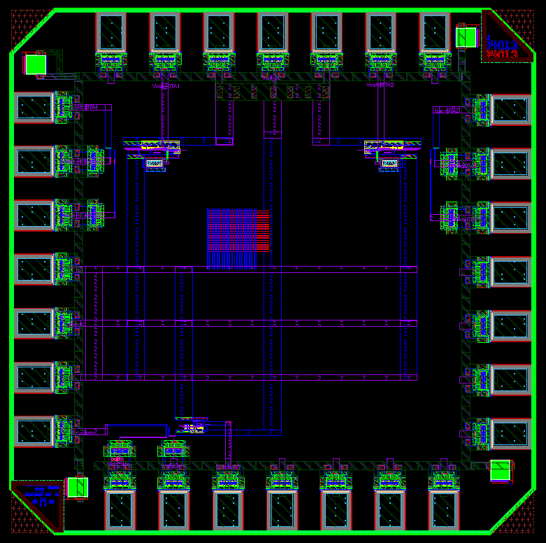
Figure 13. IC top-level layout
Figure 14 and 15 show the layout of the OTA and the comparator respectively. As a general pattern, the input signals enter from the left and exit at the right.
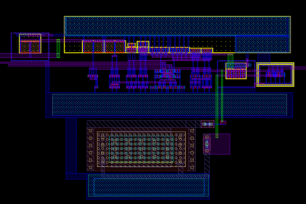
Figure 14. OTA layout
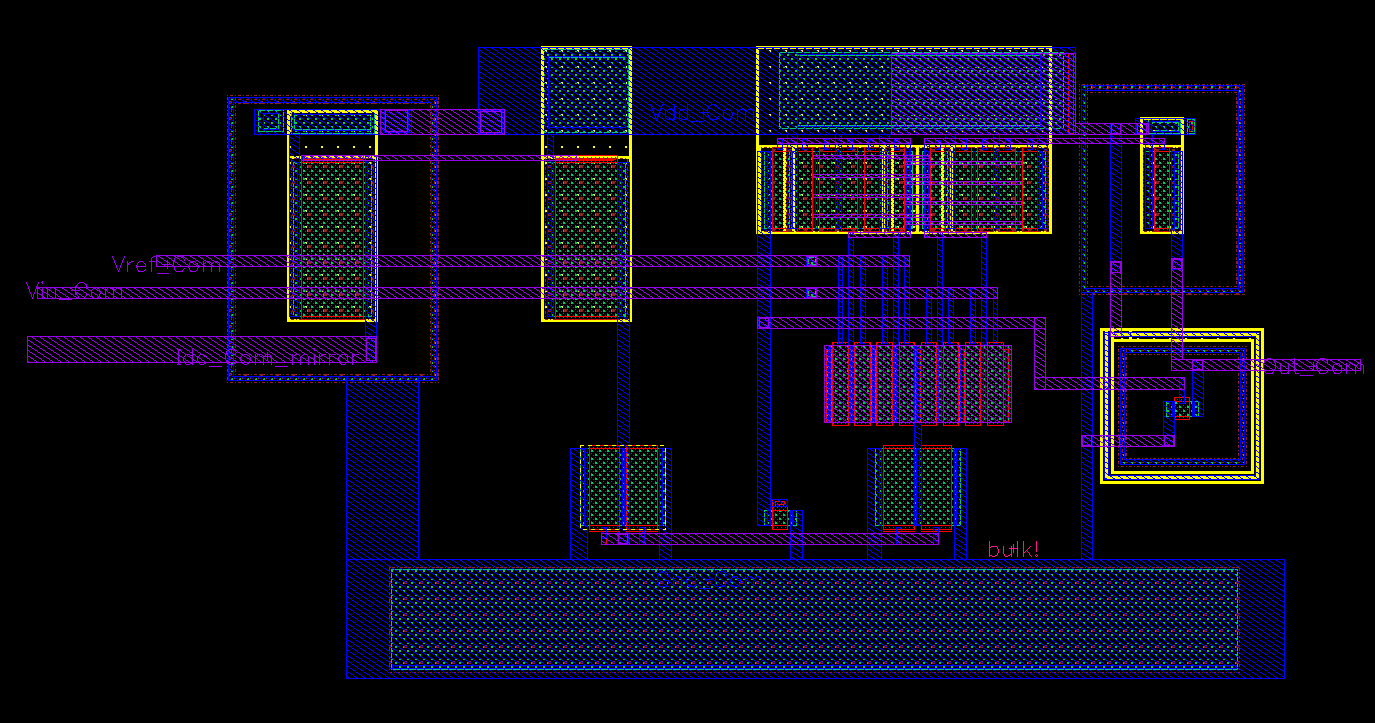
Figure 15. Comparator layout