
Die Auto-Place & Route
Automatic Placement and Routing
The filter netlist of standard cells was imported into Cadence Encounter where the die geometry, power distribution and placement floorplanning were quickly defined using graphical design tools. Die planning sets the die aspect ratio and utilization factor. Power planning sets the VDD and GND power rings to distribute power around the die. Floorplanning “partitions” constrain the die location of top-level blocks in the hierarchical HDL design. This methodology uses floorplanning to limit trace lengths, thereby reducing trace parasitics. It also provides the ability to achieve symmetry for differential circuits. It can further provide crosstalk control, but this has not been used in this filter design, however the use of this feature will be considered in future designs.
The filter floorplan partitions in Fig. 9(a) shows the 12 transconductors constrained around the centerline for differential signal symmetry and limited trace lengths since they are highly interconnected. Adjacent to the transconductors are the main capacitors to limit capacitor lead resistance. The trim capacitors are placed furthest since their trace resistance is less critical. The digital logic cells are arbitrarily placed to the left edge in an empty area since parasitics are not an issue thanks to a robust clocking scheme. The entire filter floorplanning process took on the order of an hour.
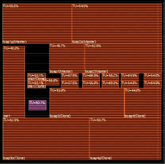
Fig. 9(a). Floorplan of the top-level blocks of the 4-th order transconductor-C Butterworth filter
Auto-placement and auto-routing took 5 seconds and 20 seconds respectively. The post-APR die design is shown in Fig. 9(b). The 12 transconductors, consisting of six inverters each are at the centerline. The large capacitors comprising the filter main capacitors are next to the transconductors. The “cloud” of tiny trim capacitors is at the top and bottom of the die. The VDD and GND power rings on the edges of the die interconnect all cell rows providing a low impedance power grid. A cloud of digital logic resides at the left-center. Standard cell decoupling capacitors can be automatically added quickly (under a minute) to fill all unused cell row spaces.
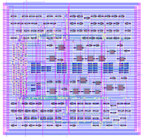
Fig. 9(b). Floorplan of the auto-placed and auto-routed layout of the 4-th order transconductor-C Butterworth filter