Testing
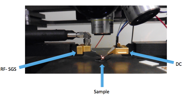
For testing this IC an on-chip probing set-up was required, the reason behind it being that this chip will later on be used for post-processing applications where the bare die is needed.
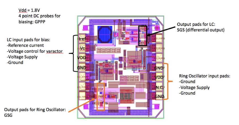
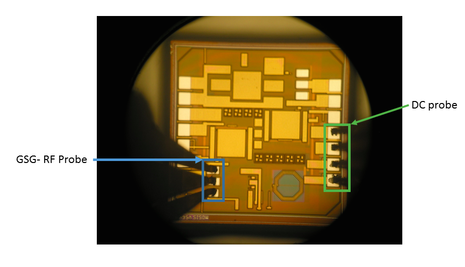
Two types of probes were needed for testing: a 4-point DC eye-pass (to provide supply and bias voltages ) probe and a 3-point RF probe for oscillator output measurement. The probing configuration (i.e. chip pads on which the probe pins are placed) is varied depending on the circuit being tested. For the ring oscillator the a ground-signal-ground (GSG) probe was used whereas for the LC oscillator a signal-ground-signal (SGS) probe was required due to the output being differential.