System Overview
System Overview
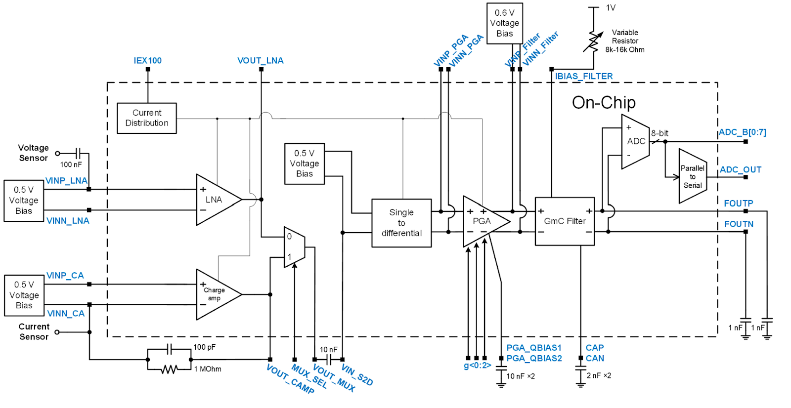
The system-level block diagram of our chip can be found in Fig. 1. As our chip is designed to be compatible with both voltage-based and current-based ultrasonic sensors, we implement a selectable input stage so that the input to the chip could be chosen between either sensor. The voltage-based sensor signal is fed into a Low-noise Amplifier (LNA), while the current-based sensor signal is input into a charge amplifier (CA). The output of both amplifiers then go to a multiplexer (Mux), where the input stage could be selected using a control signal MUX_SEL. Whichever signal was chosen by the Mux, is then passed on to the single-ended to differential converter (S2D). The S2D transforms the single-ended sensor inputs into a differential output. After the S2D, the newly differential signals enter the programmable gain amplifier (PGA). The PGA has 8 separate gain states, ranging from the lowest gain (000) to the highest (111). The gain is programmed with a 3-bit digital bus g<0:2> which sets the gain level. The differential output of the PGA is then sent to the gm/C filter which is the final analog stage. The filter has a designed cut-off frequency of 70kHz and features a tunable resistor pin, IBIAS_FILTER which allows users to make fine adjustments to the cut-off frequency in the presence of heavy process variations. The final part of the system is an 8-bit SAR ADC. This block was designed by ELEN6350 Team 3 - Doppelganger. Please see their page for a more detailed description of the design process.
Modeling of Ultrasonic Sensors
Voltage-based sensors
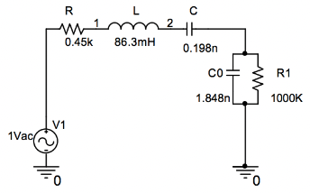
We chose the Murata MA40S4S 40kHz ultrasonic transducer as an example for the voltage-based sensor for our design. The following model was used to represent the voltage-based ultrasonic transducer in the simulation, referring from EE6350 Spring 2014 Ultrasonic Sensor project by Daniel de Godoy and Miguel Costa.
Current-based sensors
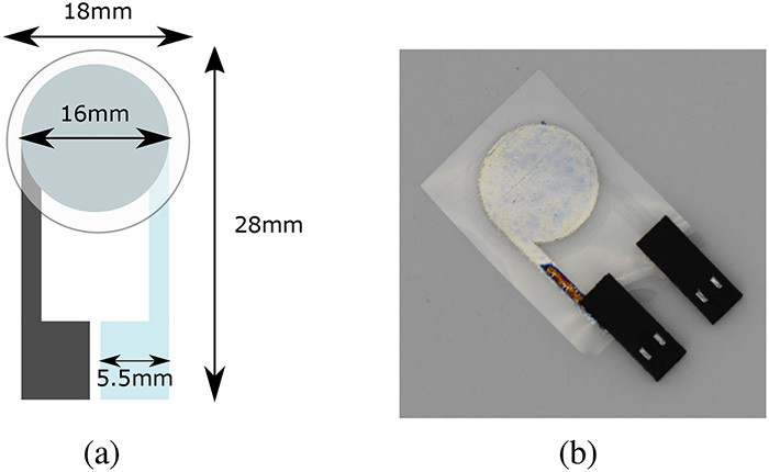
The current-based piezoelectric sensor we used is based on the work published in [2].The devices is fabricated using a polyvinylidene fluoridetrifluoroethylene (PVDF–TrFE) thin-film piezoelectric active layer with a conductive PEDOT:PSS ink.
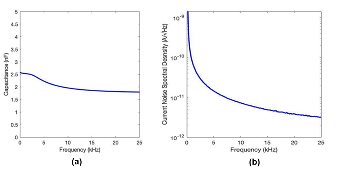
A simple circuit model for this sensor is a current source in parallel with a capacitor. To measure the value of this capacitor, the sensor was hooked up to an Agilent 4294A Impedance Analyzer and its capacitance was measured as a function of frequency. Additionally, the sensor’s low frequency current noise spectral density was measured using an insulated, anechoic chamber made with thick metal walls to reduce acoustic and electromagnetic interference, a SRS low-noise pre-amplifier to amplify the generated noise current, and a spectrum analyzer, to measure the noise spectral density of signals in the range 40 Hz to 25 kHz.