
Implementations
OTA
Figure 1 shows the OTA used as integrator in class-d audio amplifier. This OTA use the folded-cascode with active load. M5 and M6 consist a current mirror to take advantage of the current through M16. Overdrive voltage of each transistor is about 0.2V for the sizing. Cascode transistors are used to achieve a high gain. Bias circuit for Vtail, Vb1, Vb2 and Vb3 are explained in the next block.
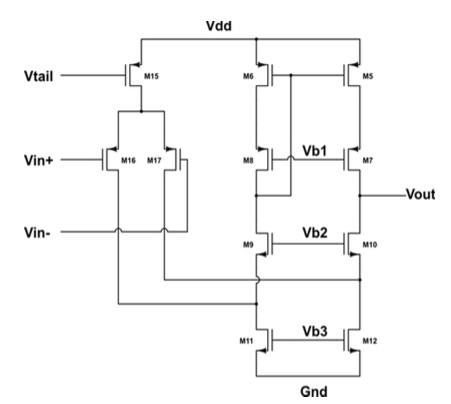
Bias
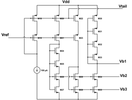
Figure 2 demonstrates the bias circuit for the folded-cascode OTA. Similar to the strong inversion case, the diode-connected transistors are used to generate the Vov. The Sooch series transistor pairs are used to generate the 2Vov + Vth such as Vb1 and Vb2. An external current-source of 100uA is used.
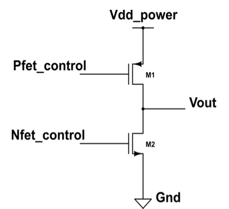
Output stage
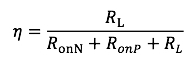
The output stage consists of two transistors with separate control signal to drive the speaker. In order to improve the efficiency of the output stage the Ron of the transistors should be small.
In general
Comparator
Figure 4 shows the schematic of comparator, which uses the internal positive feedback to increase the speed. The positive feedback devices are M5 and M8. M14, M15, M12, M13 is the second stage to amplify the output from the positive feedback.
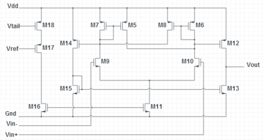
Assume the Vin- is zero and Vin+ is much lower than zero, then M7 is on, M5 is in triode region, M8 and M6 is off. As Vin+ begins to rise, the current in M5 (i5) would like to source the current in M7, following the equation
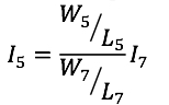
When the current in M5 is equal to current in M5, trip point will occur. In this design, the comparator does not need hysteresis, so in the ideal case we can size the M7 equal to M5, thus the trip point occurs at Vin+ equals to Vin-. While in the real case, we need to make the size of M5 a little bit smaller than M7 to further prevent hysteresis.