System Overview
In this project, we designed a closed-loop class D audio power amplifier using pulse-width modulation. Our design is a singel-channel, half-bridge load switching audio power amplifier.The analog modulator and digital logic operate from a 1.8 V supply. The modulator accepts an analog input signal and generates a switching output to drive speakers through extenal low-pass filter.
Class D amplifiers have the advantage of high efficiency and also higher THD (total harmonic distortion) compared with Class AB amplifier. So they are often used in portable devices. The implement of feedback will dramatically decrease the THD and increase PSRR.
Figure 1 shows the system level block diagram of the class-d audio amplifier.
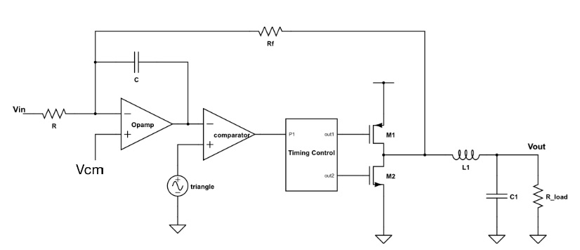
In Figure 1, the analog input signal flows into an integrator then compared with a triangular wave. The output of the comparator is Pulse-Width-Modulation(PWM) wave, and goes into the timing control block to create a dead time between the signal for the PMOS and NMOS of the output stage. Thus the time which both the NMOS and PMOS are conducted is limited and the power is reduced. The output voltage of the power stage will feedback into the integrator. The feedback ratio is defined by R/Rf.
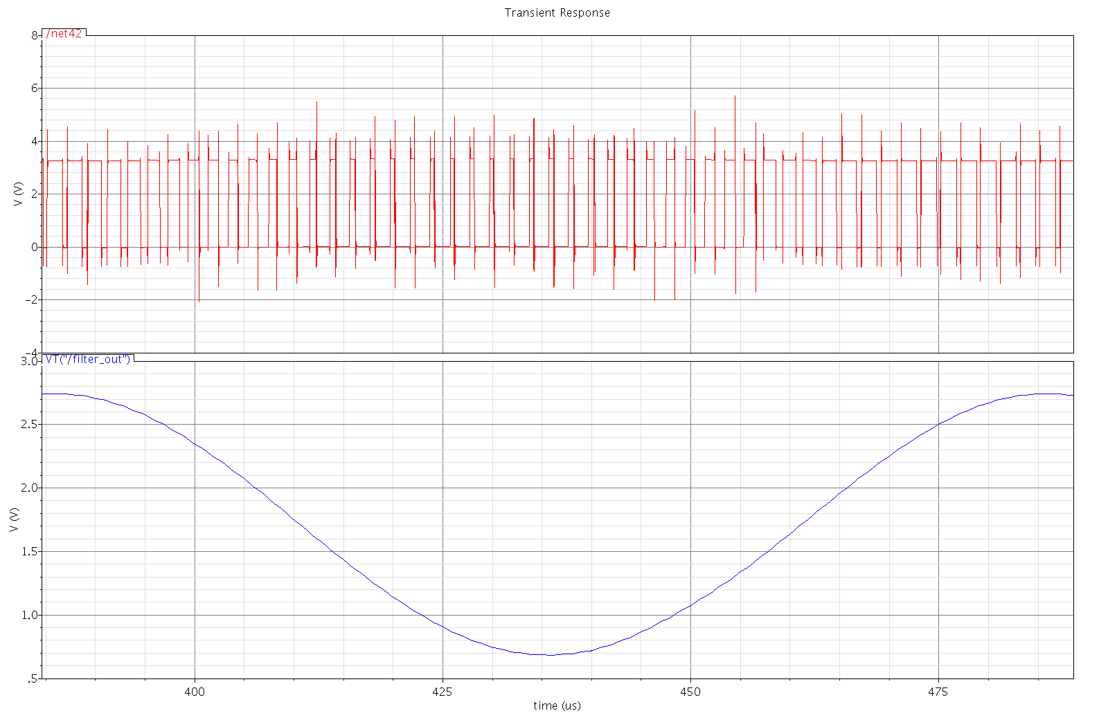
Figure 2 shows the typical output PWM signal with the output after external filter. For no input, the output PWM waveform has 50% duty cycle. As the instantaneous amplitude of the input goes positive, the output duty cycle decreases.