System Overview
Motivation
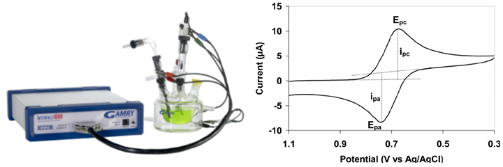
Analytical electrochemistry uses electrical methods to study reduction-oxidation (redox) properties inside a chemical system, usually a solution. Among all the techniques, voltammotry is a popular branch in electrochemistry, where a slowly varying voltage is applied through electrodes to the solution. The non-linearity and hysteresis of the output current signal against the input voltage carries important information about the redox-active composition of the solution. However, as the concentration of the redox-active solute becomes lower, the current goes lower as well. In a typical biology related applications, this current can easily goes down to pico amperes, or even into femto ampere regime.
System Requirement
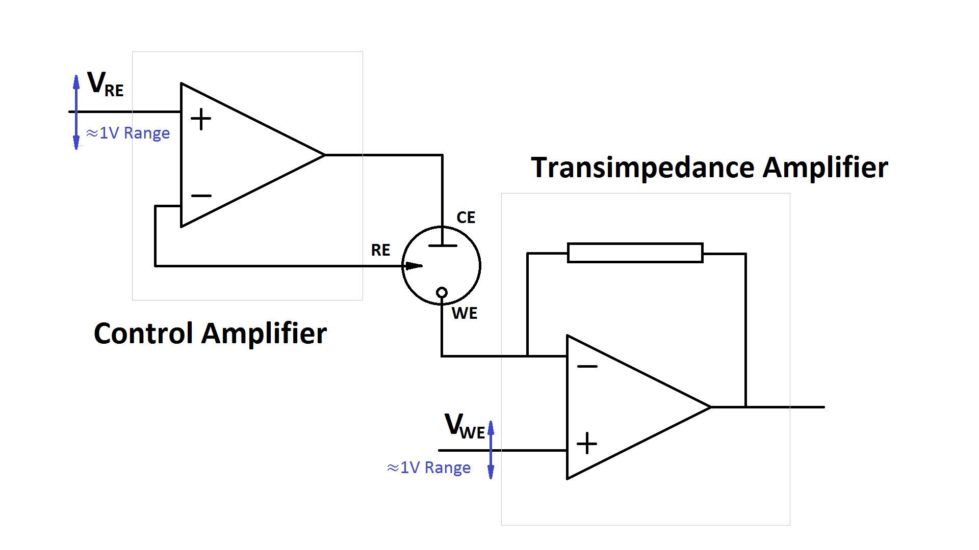
Electrochemical measurement usually requires a wide voltage sweeping range to capture information about all redox-active species in the solution. This is usually implemented using two amplifiers: a control amplifier that sweeps the voltage, and a transimpedence amplifier amplifies the current, with a fixed voltagte at its input. Limited by the technology's low supply voltage, a 1V sweep range would mean that both of these amplifiers needs to be able to work almost rail-to-rail in terms of the input commom mode voltage.
The voltage sweep carried out during electrochemical experiments are genenrally very slow, which usually lies in 1Hz to 10Hz for normal operation, or in kHz range for fast operation. The minimum current sensitivity is determined by the integrated noise level. Although a lower bandwidth gives a lower minimum sensible current, the presence of flicker noise, whose power increases as frequency goes down, make it harder to work with lower frequency range. For this design, the system is targeted at measureing tens of picoamps in a 10kHz bandwidth. And a lower noise spectrum at lower frequencies.
Considering amplifying 10pA from the input, the output needs to be sufficiently large to be capturable by and ADC. For 1.2V supply voltage, consider a 14 bit SAR ADC is used at the end, this means the output voltage needs to be at least 73uV. Or equivalently, the trans impedance amplifier needs to have a gain more than 7.3MOhm.