System Overview
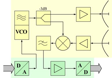
Frequency-Modulated Continuous Wave Radar (FMCW Radar) is a special type of radar which can change its transmitted frequency during the measurement. The principle of operation is illustrated in the figures below. Through a DAC which is generating the modulating signal for the radar's VCO, the transmitted signal is a chirp signal with its frequency sweeping linearly from the lowest frequency to the highest frequency. Part of the transmitted signal will be mixed with the received signal, which is the exact same chirp signal with a small time delay determined by the time of fly. The baseband signal thus will have a constant frequency component delta_f, indicating that there is an object in front of the radar. If there is no modulation applied, the radar will work as a constant wave (CW) radar and can measure the speed of the moving object based on the Doppler effect.
Our system is trying to find out the frequency component and mapping its frequency to the corresponding distance.
For detailed theory and calculations, please refer to here.
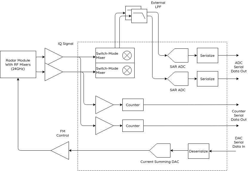
This project intends to design a baseband processing circuit for a 24GHz FMCW radar. The proposed block diagram is shown below. Three main parts are presented in the diagram:
(1) A current summing DAC and a deserializer will read the data from the FPGA and generate a triangular wave to modulate the VCO of the radar front end.
(2) A sweeping spectrum analyzer will first mix the input I, Q signal with a pulse width modulated sinusoid LO with the frequency of the sine wave sweeping from 500 Hz to 25 kHz in the period of 500 ms. After down-converting all the frequency components within the baseband signal to DC, an anti-aliasing filter and two 8-bit SAR ADC will sample the data and send it back to the FPGA for further signal processing.
(3) A zero-crossing counter will count the time difference between the two zero-crossing points when the radar is operating in the doppler mode, i.e., no modulation is applied. From the time difference, the frequency of the sine wave within the baseband signal will be calculated and thus the speed of the object can be calculated.
The chip accepts two in-phase and quadrature IF pairs generated by the 24GHz FMCW RF front-end and creates digitized signals containing distance and velocity information which will be sent to the following FPGA for further signal processing.