
System Overview
The IC design consists of six Operational Transconductance Amplifiers as well as two comparators. The OTAs were used to extract and amplify useful information in AC component (heart rate or respiratory rate) and comparators were used to produce the square wave output digital signals. Moreover, we also need High pass and Low pass filter to filter out the DC signal and harmonics signals to get the desired Heart rate signal (around 2Hz) and Respiratory Rate signal (around 0.2Hz). The OTAs and comparators in the filter path were all realized on the chip and the passive components required for transfer function realization were off-chip.Our system operates at 1.0V supply voltage and uses a reference current of 20uA.
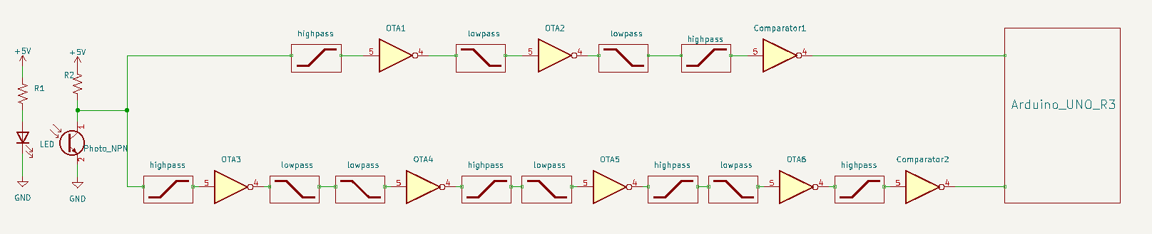
Fig. 1. System Architecture
As shown in Figure 1, our system level design consists of two Path, one is for heart rate signal and the other is for respiratory signal. The signal first acquired by the LTR-4206E sensor, we insert some high/low pass filter to reduce the effects of the noises as well as the DC and disinterested AC frequencies. We expected the user’s heartbeat to be between 30 to 120 times per minute and breathing rate between 12 to 30 times per minute, which corresponds to 0.5 to 2 Hz for heart rate and 0.2 to 0.5Hz for breathing rate. The Heart rate signal path consists of two OTA and one Comparator. The Heart rate signal path has high-pass filters with cut-off frequency around 0.48Hz and low-pass filters with cut-off frequency around 4.07Hz to get our desired signals. We use two OTAs to provide 100 times amplification to heart rate signal. The respiratory signal consists of four OTA and one comparator, the respiratory signal path has high-pass filters with cut-off frequency around 0.059Hz and low-pass filters with cut-off frequency around 0.32Hz to get our desired respiratory signals and provide 900 times amplification to respiratory signal. Figure 2 shows our system level circuit, note that at this circuit the input signal is not from real user’s input, we simulate the system behavior by adding up three signals, Signal 1: Frequency = 5Hz Vmax = 1mV, Signal 2: Frequency = 0.2Hz Vmax = 0.2mV (for respiratory rate simulation), Signal 3: Frequency = 2Hz Vmax = 2mV (for heart rate simulation).
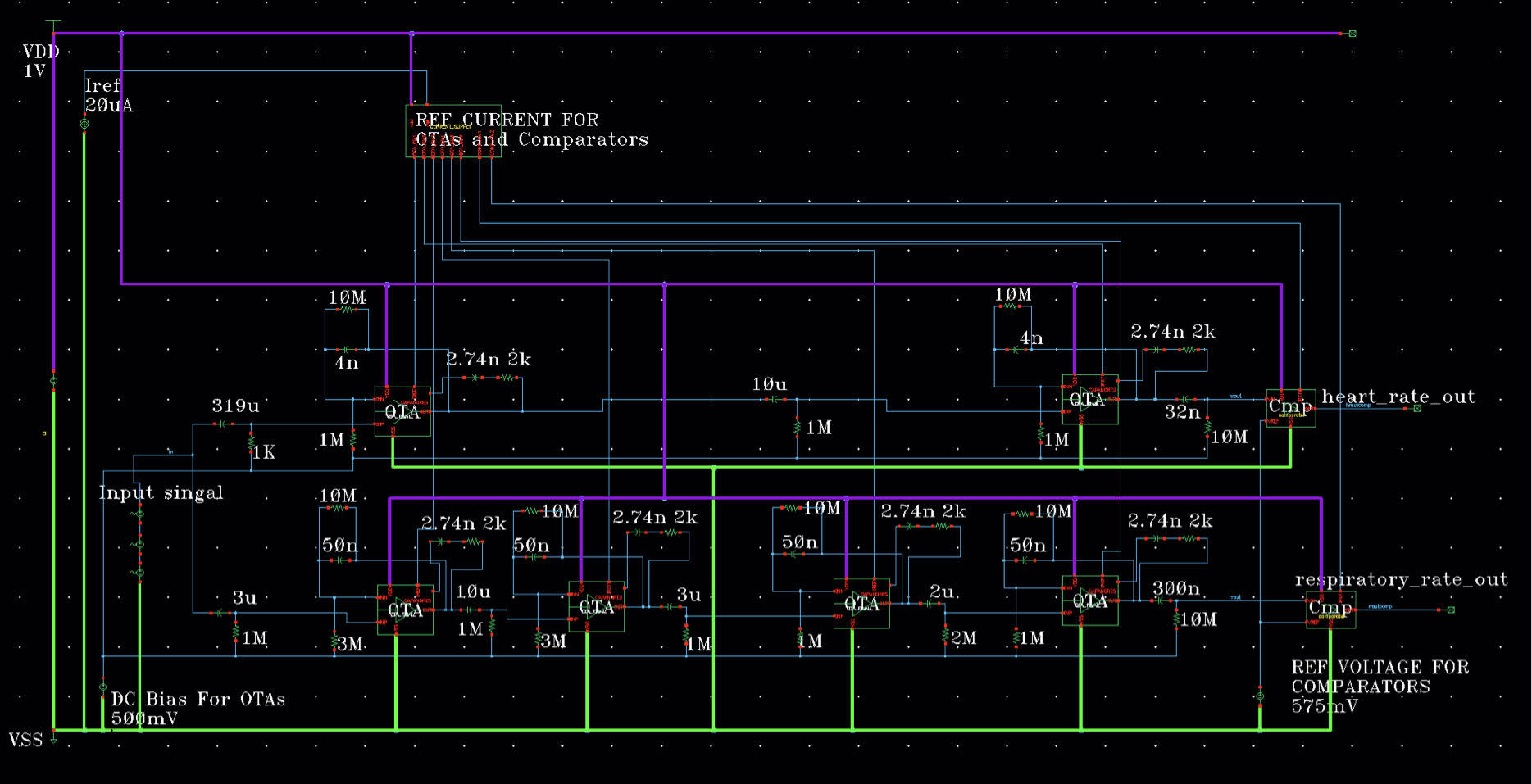
Fig. 2. System Level Schematic Design
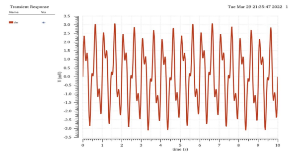
Fig. 2. Simulated Input Signal, Signal 1: Frequency = 5Hz Vmax = 1mV, Signal 2: Frequency = 0.2Hz Vmax = 0.2mV (for respiratory rate simulation), Signal 3: Frequency = 2Hz Vmax = 2mV (for heart rate simulation)
Figure 3 shows the simulation results of the Heat rate path across different process corner, the simulation results show the output of the second OTA and Comparator, the heart rate signal was clearly filtered out. Similarly in Figure 4, the simulation results of the respiratory rate path across different process corner, the simulation results show the output of the fourth OTA and Comparator, the respiratory rate signal was clearly filtered out.
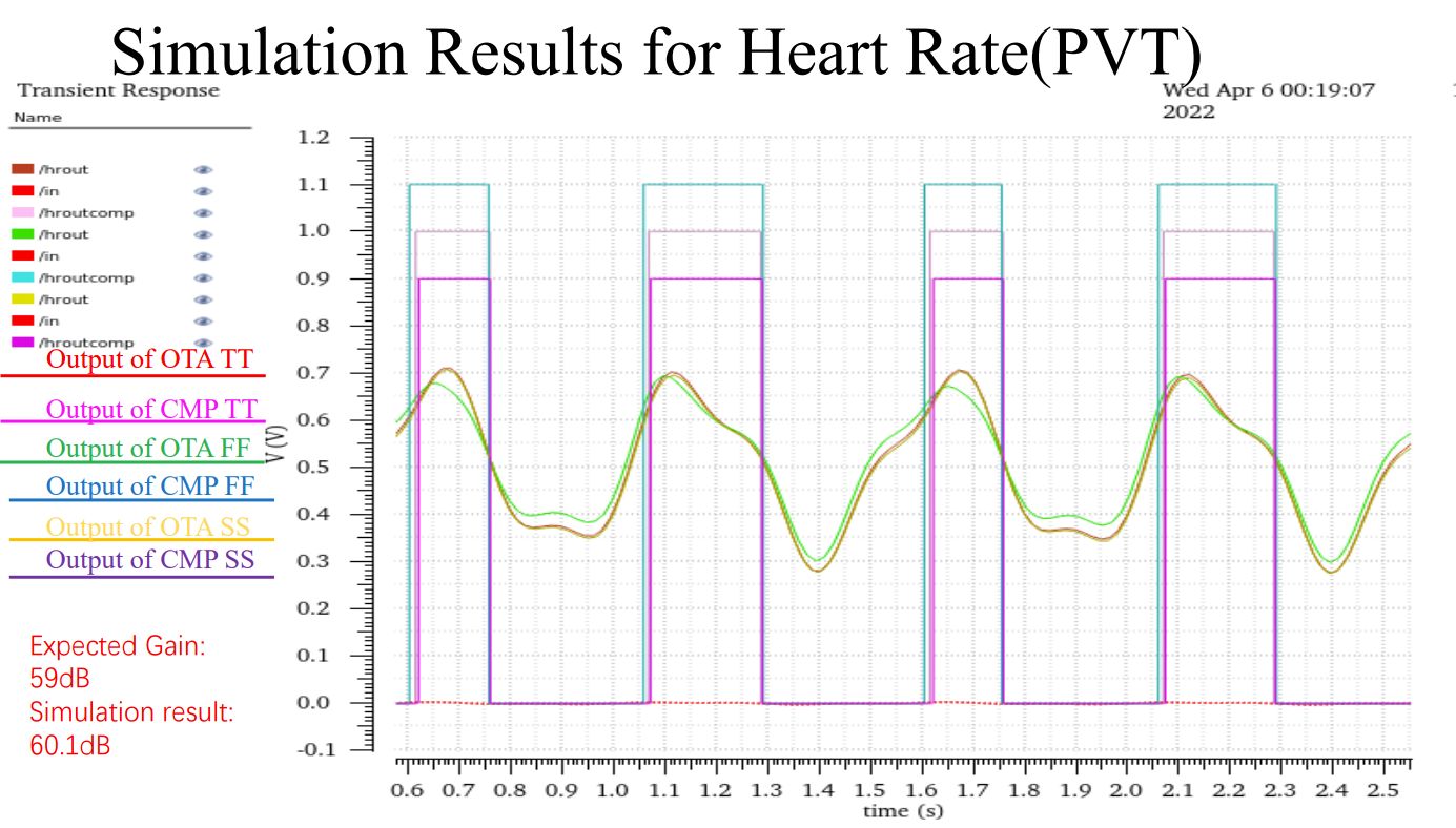
Fig. 3. System Level simulation results for Heart Rate
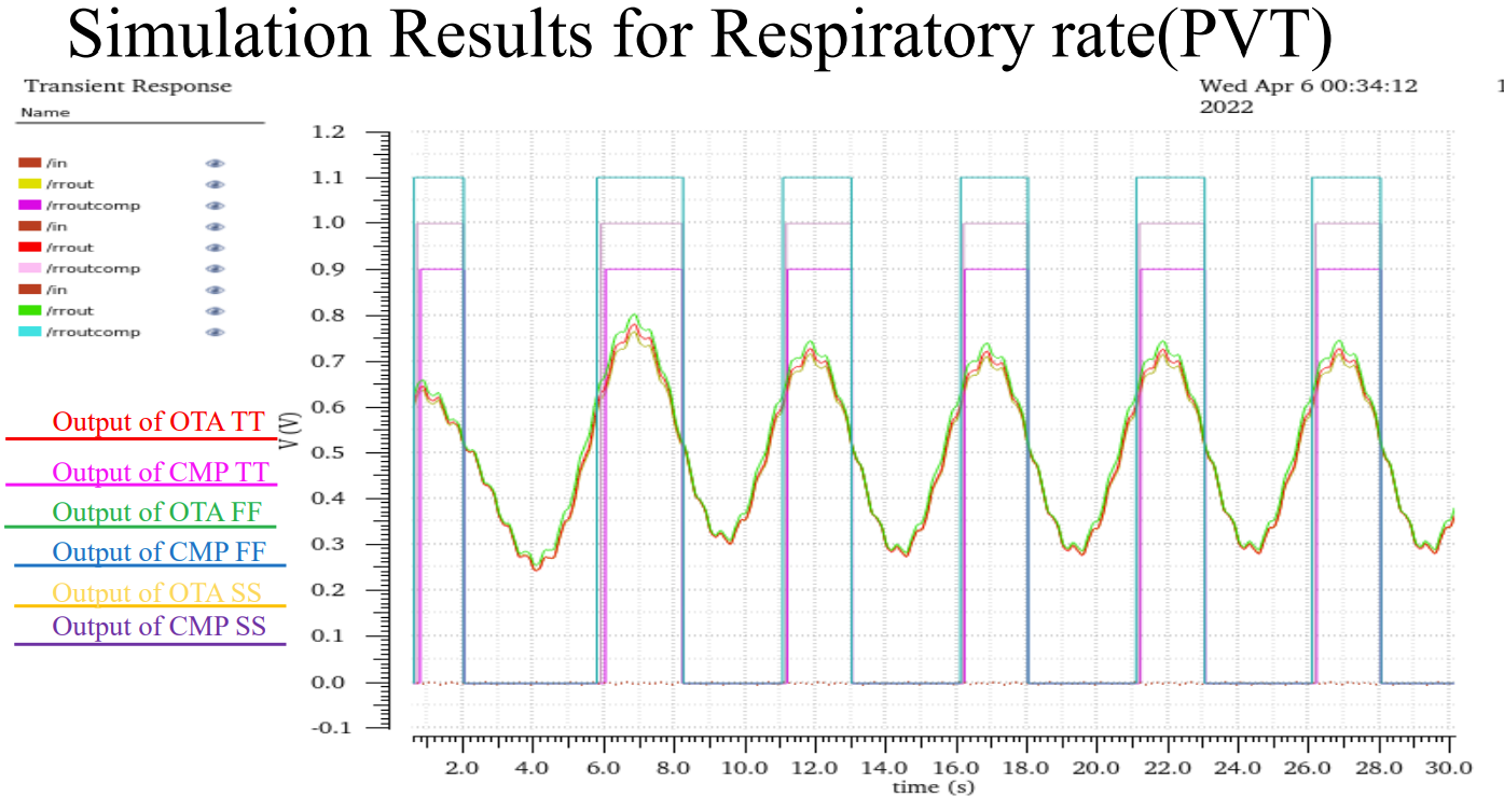
Fig. 3. System Level simulation results for Respiratory Rate