
IC Layout
Figure 9 shows the top-level layout of our chip. Each OTA and Comparator have corresponding ground, power input and reference current for better control. At the output of each comparator, we insert one output buffer for signal stability. Also, we insert 10uF capacitor between the power and ground as the decoupling capacitor to improve the stability.
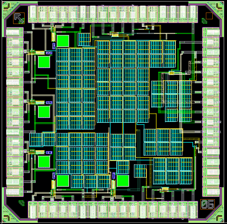
Fig. 9. Top-level Chip Layout
Figure 10 shown below are layout of the OTA.
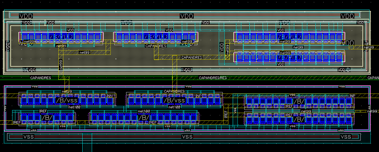
Fig. 10. OTA Layout
Figure 11 shown below are layout of the comparator.
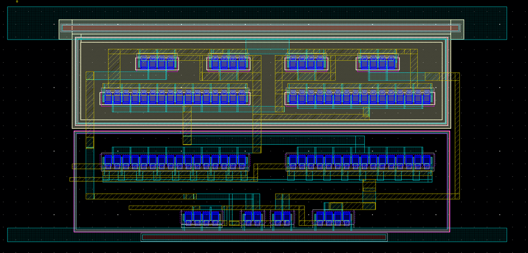
Fig. 11. Comparator Layout