
IC Design

Figure 1 shows the top level schematic of uD6350.
System Components
1) Addressing Logic: This block consists of shift register, latch and instruction decoder. It accepts and decodes the 32-bit instructions fed serially from the external source using SDI, SCLK and SLAT pins. The instruction consists of a 5-bit row address, 20-bit column data and 4-bit PWM duty cycle. See System Overview for the instruction format. At the end of an instruction transfer, the SLAT pin is asserted high. 20-bit row data is loaded and stored in the memory at the address defined by the 5-bit row address, and 4-bit PWM duty cycle value is loaded into the PWM block.
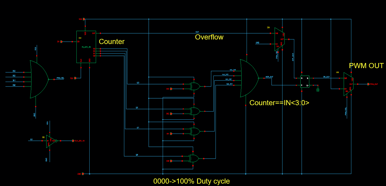
2) PWM Generator: Figure 2 shows schematic of the PWM generator. The PWM generator can generate up to 15 levels of varying duty cycle signals based on a 4-bit PWM data input. Brightness control via PWM in uD6350 is only enabled if PWM_EN input is asserted high. The SCLK pin of the serial data input provides the clock for the PWM block. The fourth output of the counter in the PWM block is used as the clock source of scan generator. This makes the display scan over a row every 16 clock cycles.
3) Scan Generator: The scan Generator is made of a ring counter, which is a series of flip-flops chained together as shown in Figure 3. The output of the last flip-flop is fed back to the input of the first flip-flop. This allows for the behavior of sequentially scanning through each row of the passive matrix. Using a ring counter simplifies the logic if additional scan signals are added for additional columns. However, during power up, the first flip-flop must be guaranteed to set, while the rest is reset. Reset block ensures this.

The block combining Scan and PWM generator is shown in Figure 4. It generates 20 scan signals, SCN0-19, for multiplexing 20-bit column data, COL0-19. When SCN0 signal is high, 20-bit data for COL0 is loaded from the memory to the column driver. Similary, when SCN1 is active, 20-bit data for COL1 is loaded from the memory to the column driver. This process continues for 20 columns in total and then the cycle repeats. Each scan signal is active for for 15 clock cycles, then 1 cycle of dead time is introduced by synchronous delay blocks to ensure that two adjacent scan signals do not overlap. This prevents garbled images from appearing on the display. See Figure 5 for non overlapping SCN and PSCN (PWM_SCN) signals. SCN0-19 signal is combined with PWM signal to generate PSCN0-PSCN19 signal which drives the row drivers. Moreover, varying PWM duty cycle varies the duty cycle on 20 row drivers.
If the CLK2_SEL input is asserted high, the clock source of the scan generator is switched to CLK2. This feature is optional and intended for testing and troubleshooting purposes.


4) Reset: The reset block resets and initializes the counters and flip-flops of the PWM and scan generator blocks. RST pin is active low. When RST is asserted high, the scan generator and PWM generator are initialized to proper state and the display starts running.�
5) Memory: The memory is made up of 400 1-bit flip-flop cells arranged into 20 rows of 20-bit words. The key feature of the memory is that it has completely separated read and write functions. This is because the drivers must constantly read out the values in the memory while the device is running, but at the same time, new values may be written into the memory asynchronously as new instructions arrive. Separating these functions allows for the two logical halves of the circuit to be completely independent of each in terms of timing. Since no standard cell was available with this capability, we designed our own memory array, optimizing to minimize device area and ensure readability and writability.
6) Column Driver: The column driver is made up of 20 PMOS devices which pull up the voltage on the anodes of the LEDs they are connected to when enabled. The devices have been sized to operate in the triode region and provide a current of approximately 1.2 mA when the LEDs are forward biased.
7) Row Driver: The row driver is made up of 20 sets of 20 NMOS devices connected to the cathodes of a row of LEDs. Since the row drivers must sink a variable amount of current depending on the number of LEDs which are on in a given row, the 20 devices within each row are enabled based on the column data, COL0-19. This ensures that the current through a given LED is the same regardless of how many others are on at the same time which in turn allows the display to have a consistent brightness when showing different images instead of having a brightness droop when more pixels are on.

Key Areas of Design
Due to the voltage and current requirements to drive an LED, we needed to use the high voltage 2.5V devices instead of the standard 1V devices in the TSMC 65 nm process which was chosen for the class. Although this was only technically required for the driver transistors, we made the decision to design the whole chip with 2.5V devices to avoid having to create separate VDD domains and handle logic level shifting between them. Since no synthesis tools were available for the 2.5V devices, all circuits were created by hand at the transistor level. Similarly, all layouts had to be completed manually as well. This made us consider the small details of the design more deeply which enhanced our understanding of digital circuit design.
Usually in digital circuits, minimum channel length allowed by the technology is used for the transistors to minimize the area. (W/L) ratio for NMOS is usally 1-1.5 and (W/L) ratio of PMOS scaled accordinly [2]. In our case we have used (W/L) ratio of 1.8 for NMOS and scaled PMOS twice the size of NMOS.
Basic flip-flop used throughout the IC is shown in Figure. The flip-flop is made of two transmission gate based latches connected back to back. The clock is buffered locally and clock bar is also genetrated locally. The output of the flip flop is buffered and designed to drive upto four of the same flip-flops.

Generally when two flip-flops are connected with some combinational logic in between as shown in Figure, the propagation delay of the combination logic has to be less than the clock period minus clock-to-q delay and setup time as shown in Eq.1.


However, in our design blocks like Scan generator and shift register contain chain of flip-flops without any combinational logic in between as shown in Figure. In this case, the data from flip-flop F1 should not reach F2 until atleast the hold time after the clock edge. Therefore, the minimum contamination delay of the flip-flop can be calculated as shown in Eq.2. If the hold time is large and the contamination delay is small, the data can propagate incorrectly. This race condition can be a big issue because this condition can only be solved by redesigning the logic and cannot be solved by reducing the clock [1].


For signals that drive large capacitance, for example, serial data output and debug outputs, the buffers can be sized as shown in Figure. The first buffer has unit size, the second has x, the third x^2, and so on. Doing so, will make added delay by each buffer a constant, i.e. xCR, where C is the lumped capacitance and R is the effective output resistance. Thus, the total propagation delay is given by nxCR, where n is the number of buffers. Output pins of uD6350 is designed to drive 10-15pf load.
