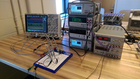
Before we have our PCBs manufactured, we powered up our ICs on a breadboard, using DC power supplies and probed the output pins on an oscilloscope.
Prototype Setup
Fig. 1: Test setup of the Digital Clock chip
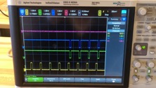
Verification of Clock Counter Increment
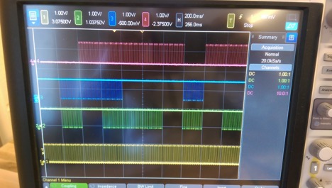
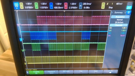
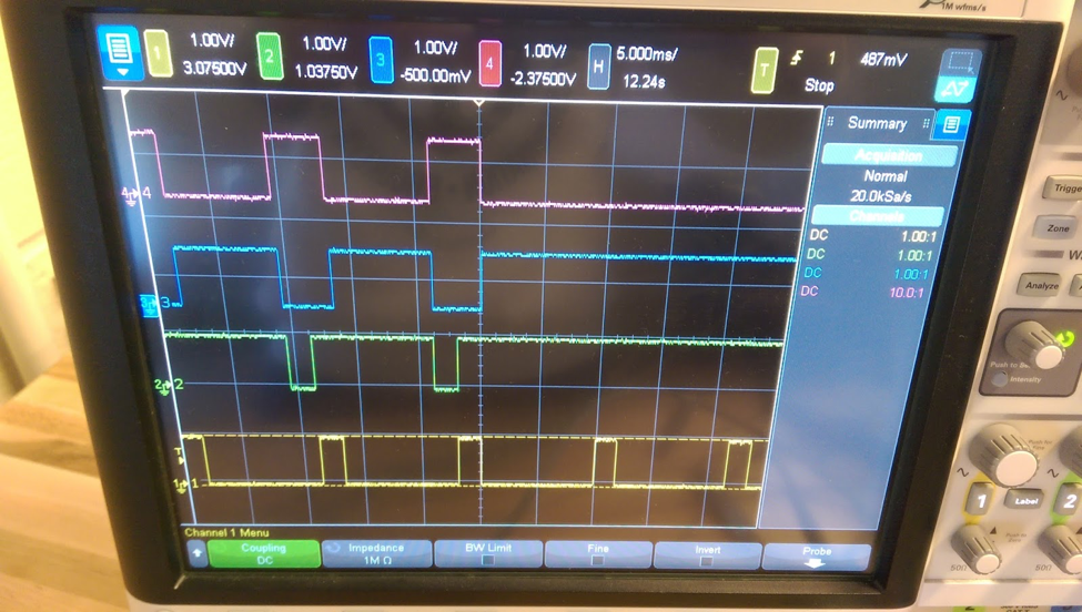
Fig. 2: Waveforms showing unit second increment from 0 to 1. Yellow (Enable 6), Green (segment E), Blue (segment F), and Violet (segment G)
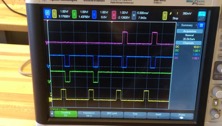
Fig. 3: Waveforms showing unit second increment from 1 to 2. Yellow (Enable 6), Green (segment E), Blue (segment F), and Violet (segment G)
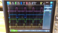
Fig. 4: Waveforms showing unit second increment from 2 to 3. Yellow (Enable 6), Green (segment E), Blue (segment F), and Violet (segment G)
Fig. 5: Waveforms showing unit second increment from 3 to 4. Yellow (Enable 6), Green (segment E), Blue (segment F), and Violet (segment G)
Verification of Time Setting Functionality
Fig. 6 Waveforms showing minutes incrementing at 5Hz in time setting mode to emulate pulsing the adv_min. Yellow (Enable 6), Green (segment E), Blue (segment F), and Violet (segment G)
Fig. 7 Waveforms showing minutes incrementing at 5Hz in time setting mode to emulate pulsing the adv_hr. Yellow (Enable 6), Green (segment E), Blue (segment F), and Violet (segment G)
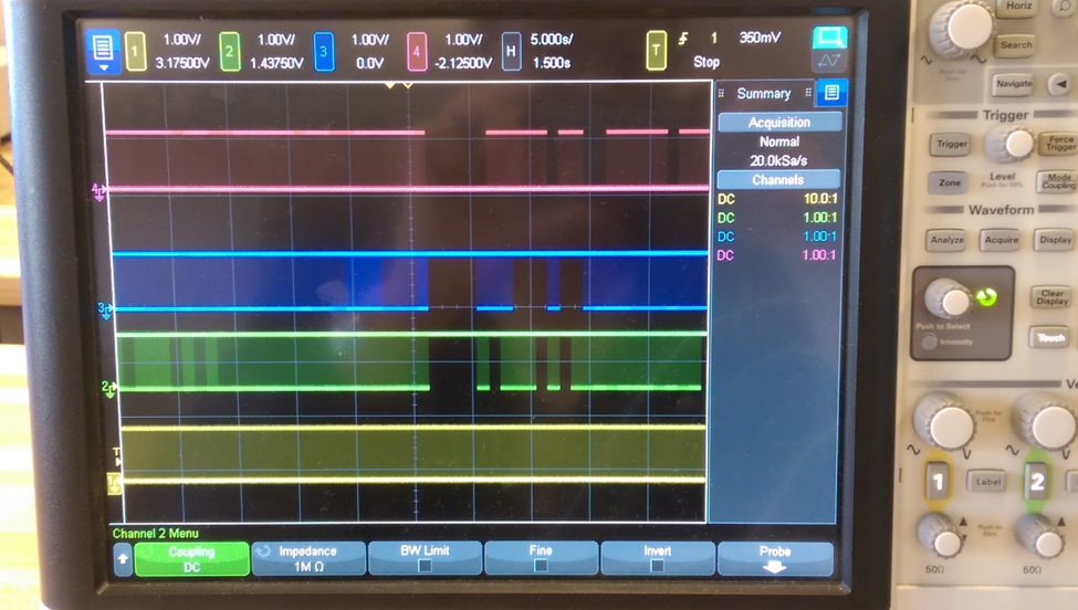
Fig. 8 : Waveforms showing clock fully resetting from 23:59:59 to 00:00:00. Yellow (Enable 6), Green (segment E), Blue (segment F), and Violet (segment G)
Verification of Clock Reset Funtionality
Fig. 9 : Waveforms showing clock resetting when global reset pin is set high at around halfway on the oscilloscope screen. Yellow (Enable 6), Green (segment E), Blue (segment F), and Violet (segment G)
Power Circuit Tests
We started by providing a stable 5V power supply at the power plug, and we converted it to 1.2V using a LDO. This was used as the VDD to the IC. We measured the VDD pin of the socket to ensure that the IC is powered at the appropriate voltage level.
Oscillator Circuit Tests
We have two on-board oscillation sources, one from the crystal resonance, and the other from an oscillator IC. Both of them generates a clock signal at 32,768 Hz. We measured their oscillation frequencies on an oscilloscope at the on-board test probe points.
LED Driver Tests
In order to tests LED driver before even plugging in the IC (to avoid the "magical smoke" at all costs), we set up the test environment to independently test the 7-segment display driver. We sweeped through all six enable signals and all seven segments to test every segment of each digit by pulling each pair of enable signals and segments to 1.2V from a DC source.