
System Overview
Using sound waves to measure distances is well known. From sonar in the old
submarine movies to the rear parking assist in your car, sound has been a powerful
but often underused resource in modern technologies. The very low
frequencies of operation, usually around 40KHz for ultrasound devices, are
very attractive to IC design, since it reduces significantly the contribution of
the parasitics of the devices. While ultrasound keeps the benefit of low
frequency, it still behaves as any other wireless system. The decision to
design the ultrasonic distance sensor not only
fits the limitations of the class project,
but also provides an opportunity to develop wireless communications system
experience.
The principle suggested for the application is similar to several sensors already
available on the market, such as PING))) from Parallax.
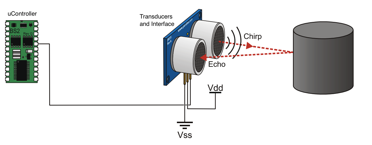
The sensor's operation proceeds as follows:
The result represents the total distance traveled by the ultrasonic wave, which, if both the sensor and object are kept still, is twice the distance of the object from the sensor.
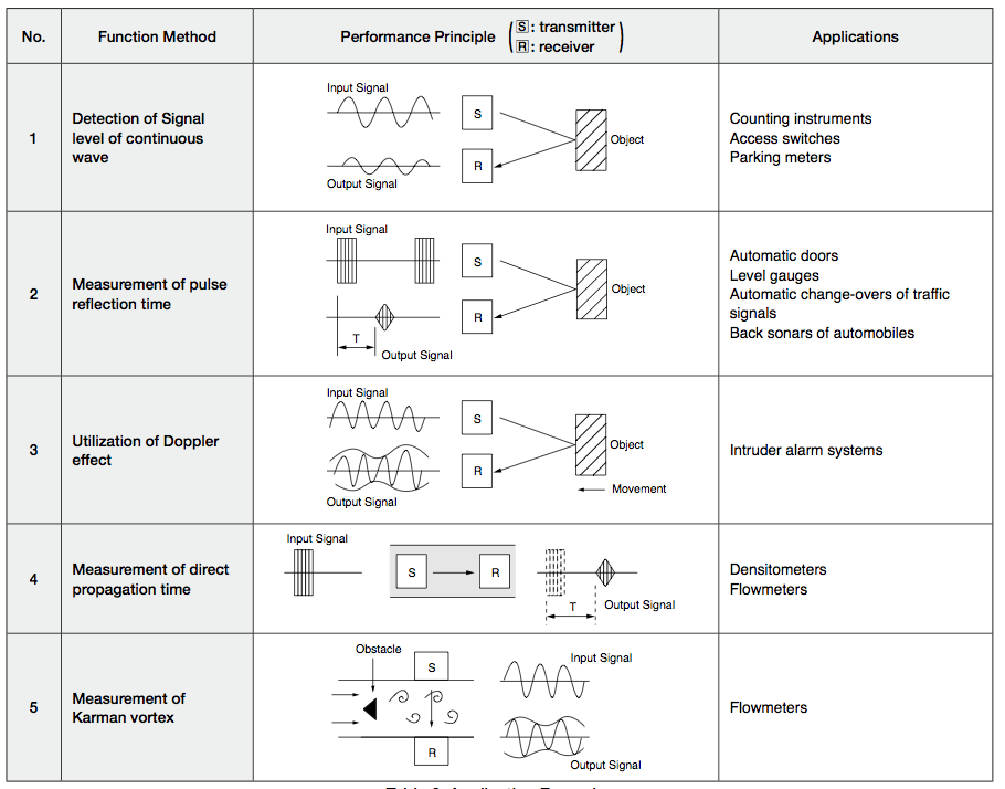
The operation described above describes the second item in the muRata Application Manual, however the DM6350 is capable of fulfilling all other functions. At the amplitude based systems (the first, the third, and the fifth items) the output of the Chip would change to the filtered signal, and an ADC is need to prepare the data to the microcontroller.
Transducer Characterization
Before starting development a preliminary study
on the behavior of the ultrasonic transducer was
made. In this project, the ultrasonic
transducers used were the
255-400ST16-ROX and
255-400SR16-ROX,
from Kobitone. The need to correctly understand
the transducer’s characteristics is fundamental
for establishing the requirements of the system
and models the input signal on simulations.
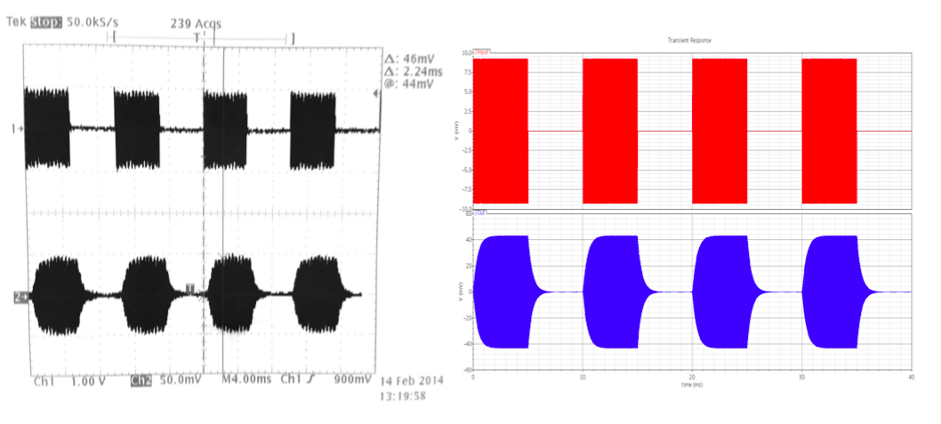
To analyze the transducer’s responses and its changes over distances, the
transmitter was connected to a signal generator, then the output signal, on the
receiver end, was measured. The results are presented below.
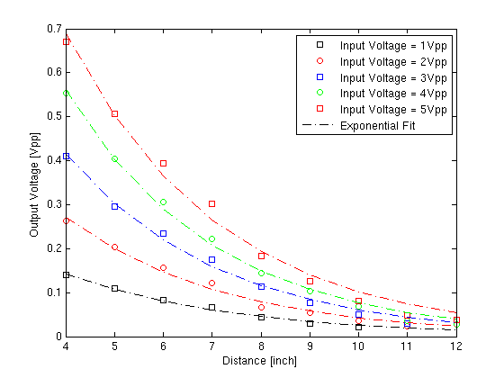
With these measurements, based at [3], an empirical mathematical expression was extracted.
Vout(d) = .9996 d-1.903V, [d] = inches
Setting the range of the sensor to 10ft, the system should be sensitive to
signal with amplitudes in the order of 100uV.
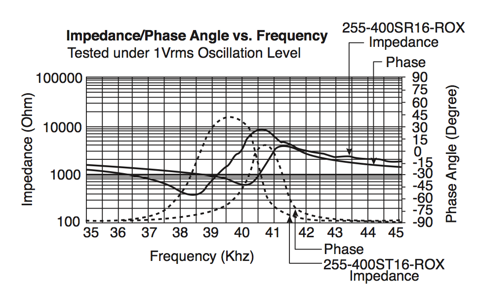
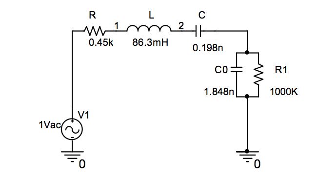
The model of the transducer that was used on simulations was extracted from the paper
MODIFICATION OF RESONANCE CHARACTERISTICS OF ULTRASONIC TRANSDUCERS BY THE DRIVING CIRCUIT.
The criteria used were that the impedance of the transducer model
should be similar to the impedance profile present at the transducer's datasheet.
System Implementation
The system is fundamentally similar to an OOK demodulator, however, in this
case, the information is extracted from the time difference between the pulses.
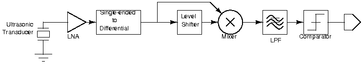
At the front-most end of the system there is a low noise amplifier (LNA), its
function is to enhance the weak signal received by the transducer without
introducing significant extra noise. The LNA gain was designed to be on the
order of 60dB.
The next two blocks treat the output signal of the LNA to properly drive the
Mixer. The Single-ended to Differential divides the signal in two branches with
similar amplitude and DC voltage, but opposite phases, while the Level Shifter
changes the DC voltage of this differential signal. This is necessary for the
correct operation of the Gilbert Cell as a mixer, since it takes differential inputs
in a transistor stack that need to be accordingly biased.
Both outputs of these blocks are applied to the mixer. Since they have the
same AC content, this process is called Self-mixing. The effect of self-mixing
in a purely sinusoidal signal is the development of a DC component and
another at twice the frequency of the original signal.
So, whenever a burst of 40KHz frequency is sensed by the Transducer,
amplified by the LNA, and applied to the Mixer, an output with an 80KHz
frequency and a DC offset is generated. The Mixer's output is also differential,
both branches are mirrored around a common mode voltage. A Differential to
Single-ended Low Pass Filter with a 20dB gain is used to remove the high
frequency components of the resulting signal and finally a Comparator
changes the overall system output whenever the filtered signal rises above a
threshold voltage.
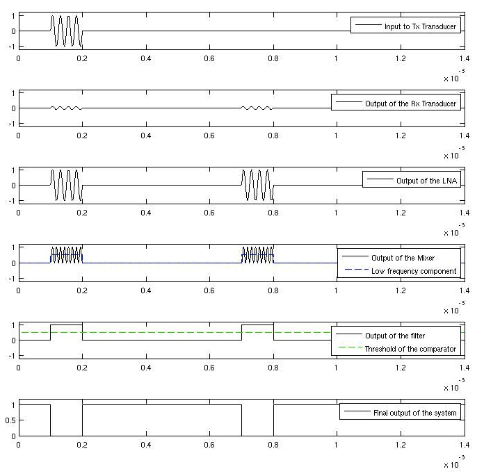
Going through the waveforms of the systems displayed in figure 9 we have: the stimulus to the TX Transducer; the sensed signal at the RX Transducer; the amplified output of the LNA; one of the branches of the self-mixed output of the Mixer; the filtered signal; and the final output of the system.