
PCB Design
In order to complete the system, we design a 2-layer PCB to host the IC and other off-chip components. The off-chip components include a 9V battery, voltage regulators, the Oximax sensor, various resistors and capacitors to form filters, Arduino microcontroller, and a LCD screen. We have four voltage regulators in total: 1.2V for IC power supply, 0.8V for comparator reference voltage, 0.6V for OTA bias voltage, and 5V for Oximax sensor and Arduino. We designed the PCB schematic and layout on the software Diptrace, with the schematic and layout of the PCB board shown on figure 16 and 17 respectively. In the schematic, one Arduino Uno R3 footprint is the actual Arduino, while the other is the LCD display, which happens to have the same pin locations as the Arduino so we used the same footprint. For some resistors such as those used for creating bias current, feedback loop in OTAs, and voltage regulators, we used variable resistors (potentiometers) to be able to adjust critical parameters to accommodate unforeseeable problems.
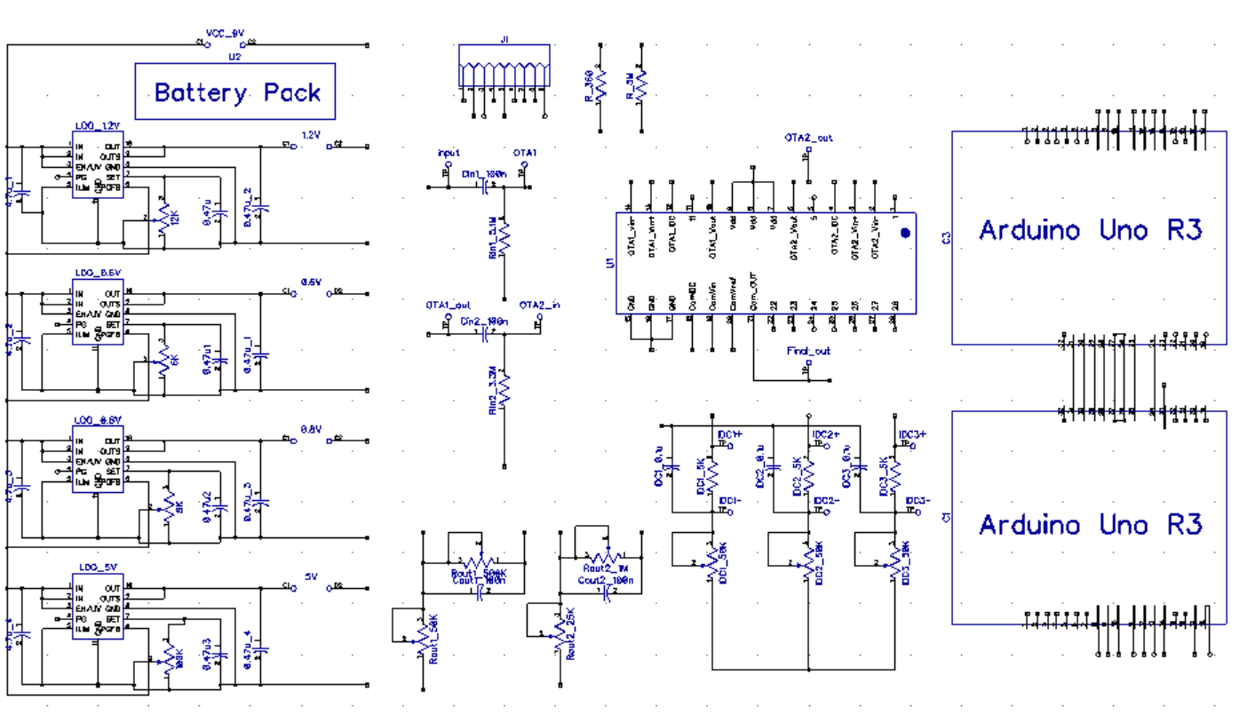
Figure 16. PCB schematic

Figure 17. PCB layout
Arduino code is used to process the comparator output and display the measured heart rate on the LCD screen. To combat measurement errors, we use a method of averaging the previous 9 heart rates and the current one to get a reading, and this averaging is done continuously to provide real-time heart rate monitoring. The system also supports displaying the instantaneous heart rate.