Using VisGenie - Demo Studio


Using VisGenie Demo Studio

Basic Operations
  Open VisGenie Demo Studio
Create New Demo Project
Create New Tool Window
Open Video File
Specify Metadata File
Render Demo Project
Link All Video Tool Windows
Save Demo Project
Open Existent Project
Customizing Tool Windows
  Video Tool
Curve Tool
Image Tool
Collection Tool
Object Tool
3D Scene Tool
Browser Tool

BASIC OPERATION

Open VisGenie Demo Studio

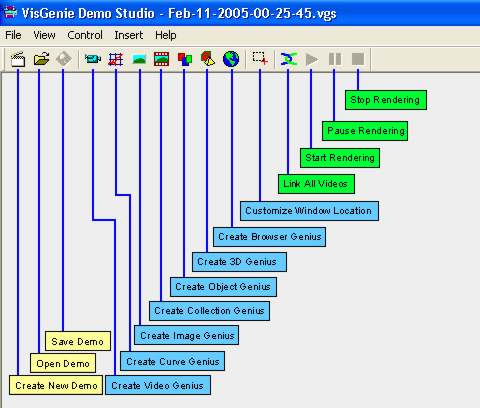
Select "[VisGenie in Start Menu] / VisGenie Demo Studio".

The VisGenie Demo Studio window will appear as follows. Try to be familiar with the tools at the first glance.


Create New Demo Project

Click on the button "Create New Demo" from the toolbar". This will open a new demo project for editing. If you are currently editing another demo project, you will be prompted to confirm whether you need to save current project.

Create New Tool Windows

Creatting new tool windows is very easy in VisGenie Demo Studio: just click on any button for specific tool windows from the toolbar.

There are two methods to decide the position of the created tool window. By default the tool window willl be created in the middle of the screen with a default size, varying depending on the tool window categories. The alternative way is to customize the window location. For this purpose, firstly switch on the "Customize Window Location" button from the toolbar. Then choose the tool window you want to generate, push the left mouse button, and drag a rectangle on the position where you want to put the tool window. Release the left mouse button, the new tool window will be created.

You can freely move the tool windows or resize them using the mouse as you do for any normal windows. You can also move the tool windows using the Left, Right, Up, and Down arrorw keys in the keyboard, which will modify the window position based on a unit of 20 points. "SHIFT"+arrow keys will move the tool windows on a unit of one point.

A tool window has several basic components:

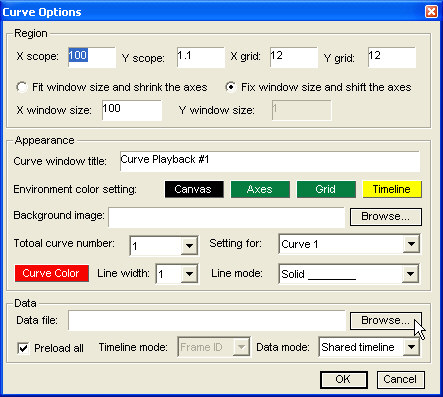
Tool Window Title: a helper description about the function or purpose of the tool window
Metadata Description: additional metadata description about the content of the tool window. In the Demo Studio, when a tool windows is associated with a metadata file, this line will be the metadata file name.
Client Region: the region where the actual visualization function is executed.
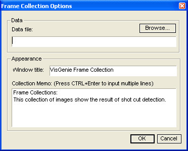
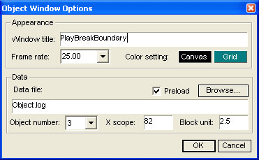
Setting:activating a menu or a dialog where you can modify some properties of the tool window, such as specifying the medata file.
The details on how to set the properties of the tool windows is introduced in Customize Tool Windows.

All tool windows can be folded by double clicking on the title bar.

Open Video File

A typical VisGenie demo project usually comprises a video window and several visualization tool windows. The video tool window is the rendering distribution center. When the video playback is launched, along with video rendering, the video tool window will distribute a synchronization signal to all tool windows in the project and these tool windows then render their own metadata and synchronize the rendering with the video playback. However, it is possible to build up a demo project purely for metadata visualization without a video window.

To open a video file, firstly create a video tool window. Then click on the "Open File" button . Choose the wanted video file. When the video is loaded, the first frame will be displayed, and the video is paused for later playback.

Specify Metadata File

Each tool window has two work mode: rendering offline metadata and rendering online metadata. The online mode visualizes the result from video processing and needs to use VisGenie SDK. In VisGenie Demo Studio, all tool windows work in the offline mode; i.e., each tool is associated with a metadata file, which is generated in advance and need to be specified manually.

To specify a metatata file to a tool window, click on the "Setting" button. Depending on the tool categories, a menu or a dialog will appear. If you see a menu, click on the "Properties..." meanu item, and the property dialog will pop up. In any case, you will be able to find an item named "Data File" and a button "Browse...". Click on the "Browse..." button and specify a metadata file. The format of the metadata file varies based on the tool categories. Please see a full reference of metadata file format specification. You can also study the built-in metadata file examples from "[VisGenie Folder]\Demos". All of these metadata files are ASCII text files and you can open them using any basic text viewer (e.g., Notepad). These metdata files are:

PSNR.log: PSNR values for each video frame, used in the demo "Quality Comparison" (See "[VisGenie in Start Menu] \ Demos" for all demos).
Circle.log : The 2D coordination values for two circles, used in the demo "Curve with Background".
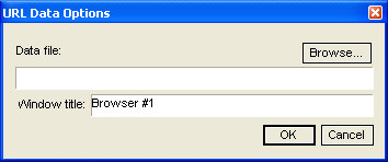
URLData.log: Some URLs that will be synchronized with video playback, used in the demo "Browser Tool".
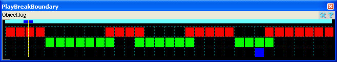
Obejct.log
: Some discrete values indicating the appearance of certain objects, used in the demo "Soccer Game Parse".
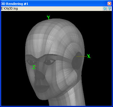
Uni3DData.log: Some 3D object data, used in the demo "Misc Tools".
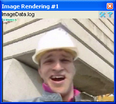
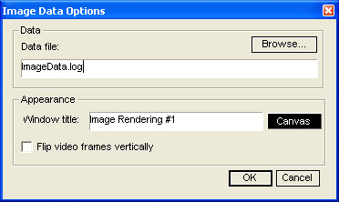
ImageData.log:
The data deciding whether to extract certain video frames or display some image files, used in the demo "Misc Tools".
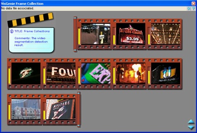
FrameCol.log: The data recording the calculated confidence of certain video frames or image files, used in the demo
"Soccer Game Parse".

Render Demo Project

When you finish building up the demo project, make sure you have at least one video window with a video file loaded. Click on the "Play" button from the video window. The project will be rendered based on current setting.

Link All Video Tool Windows

If you have more than one video window in the project, and want to synchronize their playback instead of start them one by one, you need firstly link all video tool windows together. To do this click on the "Link All Videos" button from the toolbar. The set of playback contrl buttons on the toolbar will be enabled. These control buttons are used to send the command (Play, Pause, and Stop) to all video windows so that they can playback the videos simultaneously. This feature is very helpful when you want to compare two (or more) synchronized videos.

As mentioned above, video window is the rendering distribution center, who fires a synchronization signal to all tool windows. In the case there are more than one video window, only the first generated video window is in charge of synchronization signal distribution. All of the other videos are just rendered by themselves.

Save Demo Project

You can save your demo project anytime during your project editing. To do this simply click on the "Save Demo" button from the toolbar. If you save the project for the first time, you will be prompted to choose a file name and destination location.

Open Existent Demo Projects


Clicking on the "Open Demo" button from the toolbar can let you open the existent demo projects. You can find some demo projects from "[VisGenie Folder]\Demos". If you are currently editing other project, you will be prompted whether you want to save your modification on current project before the specified project is open.


CUSTOMIZING TOOL WINDOWS

This section provides some more information about how to customize the tool windows satisfying specific visualization purposes. The contents emphasize the usage of these tool windows in a demo project. In order to know more flexibility in using these tools, please refer to VisGenie SDK.

Video Tool

.

The video tool window in VisGenie provides the basic video rendering functions as in any media players. However, it is not designed to provide full support for entertainment purpose (such as playlist, media library and subtitle), though it is possible to do so through VisGenie SDK. Instead, the video tool provides additional functionalities that is suitable for research / develop purpose.

Basic video playback control functions:

Play: Click to playback the video from current position
Pause:
The video playback is hold at current position, and can be continued when "Play" again.
Stop:
The video playback is terminated. The video tool window release all internal resources and the
Beginning:
Seek the video to the beginning of the sequence.
Previous:
Seek the video to the previous frame of current one.
Next:
Seek the video to the next frame of current one.
End:
Seek the video to the end of the sequence.
Cutin:
Together with Cutoff to define a playback range. The video rendering will be constricted within this range.
Cutout:
Together with Cutoff to define a playback range. The video rendering will be constricted within this range.
Browse:
Browse the systems and pen a video file.

Click on the "Setting" button of video window. A menu pops up. Here is the specifications of the menu items:

Open source: Open a video file, same as the "open source" button .
Save current frame: Save current frame into a bitmap file, currently only valid for RGB24 frame format. It is only enabled when the video is paused.
Save sequence as : Reserved.
Original size : keep the video frame as its original size, no matter how the size of the video tool window is adjusted.
Fit to window: Resize the video frame size along with the size of the video tool window. When resizing the aspect ratio is kept.
Play alone : Render the video by itself, without distributing the synchronization signals to other tool windows. When this setting is changed, the video file need to be reloaded manually.
Hide the information : Reserved.
Clear range selection : In VisGenie you can define the range within which the video is rendered. E.g., for a clip with 10 seconds, if the range is selected as from 3s to 5s, the video will only be rendered within 3s~5s, and at the 5th second, the video will pause and jump the frame at 3rd second. Range is selected by defining "Cutin" and "Cutout" points. When a range is defined, there will be a blue rectange shown in the progress bar. The range can be defined multiple times and only the latest selection works. In any case you don't want the range any longer, choose "Clear range selection" from the setting menu.
Properties: Active the property dialog for some advanced settings.

Click on the "Properties..." menuitem from the popup menu to set some more properties of video tool window.


Window Title : Set the title of the video tool window.
Frame Rate : Specify the video frame rate if you know it, otherwise leave it blank. This setting will not change the actual video rendering rate. Instead it provides some helpful information to facilitate the synchronization for other tool windows. When the frame rate is not specified, the video tool window counts the frame sequence number (starting from 0) based on the playback order. This might be a problem when some frames are skipped during video playback if the frame processing or visulization task is too complex to be finished in real time rate. However, when the frame rate is set, the video tool window calculate the frame sequence number based on the timestamp and the frame rate, which is much reliable for tool window synchronization. If you know your visualization task will take a long time, you are suggested to specify a correct frame rate. Otherwise just leave it blank.
Preferred image format: Specify what image format you want to process. This is also the format you get in the pixel domain after the video is decoded. Usually you need to set this property if you want to have some image processing in your video analysis application. For VisGenie Demo Studio, you don't need to change this, unless you want to dump video frames into bitmap files, where you need to set the format as "RGB24". Also make sure you understand the image format before you choose it. Please note depending on the codec, not all formats in the list are supported by the decoder. To check whether your system supports a specific image format, set it and reload the media data manually, and see if the video can be reloaded successfully (you can see the image format from the clip information in the video tool window) without errors. The safest format is RGB24 which is supported by nearly any video codec.
Use the synchronization clock: Synchronization clock is used to control the video rendering speed. For each video frame, there is a timestamp information associated, indicating when the frame will be displayed and how long it will last. E.g., if the video is of 25 frame per second, every 40ms the frame will be changed to the next one. If the synchronizatin clock is switched off, the video will be rendered as fast as possible, meaning the current frame will be changed as long as the next frame is ready (decoded). In another words, in some situations when the processing for each frame needs very long time, it can guarantee a frame-by-frame display and process without any frame skipping. This is a very useful feature for some video analysis applications where each frame undergoes heavy-loaded computing during processing. In the demo studio, you are recommended to switch it on.

Curve Tool


The curve tool window might be one of the most frequently used visualization tool. Curve tool provides a wide range of customization functionalities, from appearance to rendering modes. Please try to be familar with the concepts as shown above.

There are three basic curve rendering modes:

Preload Mode: All of the curve data will be preloaded before the video rendering. The synchronization with the video signal is accomplished by displaying a timeline. You can see the demo "Quality Comparison" for such an example. This is a suitable mode for showing demos.
Real Time Mode: In this mode the curve will only be displayed when the synchronization signal is received. I.e., the curve will be shown little by little along with the video rendering. This is helpful if you want to hide some curve data before its time. Real time mode is suitable for both demos and video analysis platforms.
Histogram Mode: In this mode the curve will be shown in a histogram bar (or probability distribution) mode. You can see the demos "VisLab" and "Shot Cut" for such examples. This is a suitable mode for video analysis platforms.

The limitatino of curve tool window: in current implementation, the curve rendering can only render non-negative data. I.e., the left bottom corner of the curve window is (0,0). This can satisfy most of the rendering requirement. In the case the negative values are absolutely needed, it can be compensated by adding a shifting value. (This solution sounds clumsy. More flexible solution is scheduled in later upgrade.)

Click on the "Setting" button of curve window, and the "Curve Options" dialog pops up.

X scope: The whole length of the x axis. This value is based on the real data, but not the pixels on the screen. Usually this value is set to be the total number of video frames for convenient synchronization. Please note the curve tool may be windowed, which is defined by the Window X size. In this case, only part of the curve falling into the window is displayed. During the rendering, X Scope might be automatically adjusted in order to fit the new coming data. E.g., if current X Scope is 100, when the new coming data has an X value of 200, the X Scope will automatically be set to a value larger than 200 so that all of the data are visible.
Y scope: The whole length of the Y axis. This value is based on the real data, but not the pixels on the screen. Note along Y axis the tool window is not windowed. Also Y S cope might be automatically adjusted in order to fit the new coming data. E.g., if current Y Scope is 100, when the new coming data has an Y value of 200, the Y Scope will automatically be set to a value larger than 200 so that all of the data are visible.
X grid: Together with Y grid, X Grid defines the size of the grid, which is based on the pixels on the screen, and therefore will not be adjusted when the window is resized.
Y grid: Together with X grid, X Grid defines the size of the grid, which is based on the pixels on the screen, and therefore will not be adjusted when the window is resized.
Fix window size and shift the axes: If this option is selected, the curve tool window will be windowed if necessary. What is shown in the curve tool is the windowed curve region. E.g., if X Scope is 300 and X window size is 100, to render the curve data with X value of 150, all data with X values less than 100 will be hidden, and the curve window shows the data starting from 100.
X window size: This value defines the window size when the curve tool is windowed. It is based on the real data.
Y window size: Reserved. Currently the Y axis is not windowed.
Curve window title: The text shown on the curve tool window title bar.
Environment color setting: Clicking on each button with a label will set the corresponding color.
Background image: Curve tool window can select a bmp image as the background. See the demo "Curve With Background" for an example.
Total curve number: The number of curves shown simultaneously. Up to 5 curves can be shown in a same curve tool window. In order to display more than 5 curves, create another tool window.
Setting for: Choose the curve you want to set the properties.
Curve color: Select the color of the curve.
Line width: Select the width of the curve.
Line mode: Select the mode of the curve.
Data file: Select the metadata file containing the curve data. See Specify Metadata File for more details.
Preload all: Set the curve tool in the preload mode. Otherwise, the curve window works in the real time mode.
Timeline mode: Reserved.
Data mode: This feature describe how the data in the file is saved. In the shared time line mode, all of the curves within one curve window will share the same X value. Usually this is the mode for demo project and the X value is the frame ID. See the file "PNSR.log" for more details. In the seperate timeline mode, each curve in a curve window will have its own X values. See the demo "Curve With Background" for such an example, where the data file is "Circle.log".

Image Tool


The image tool provides basic image (frame) displaying function. It can accept the frames from the video clip during the video playback. It can also open external bitmap files. Please see the demo "Misc Tools" that shows the usage of image tool window.

Click on the "Setting" button of image window, and the "Image Options" dialog pops up.

Window title: The text shown on the tool window title bar.
Data file: Select the metadata file containing the image data. See Specify Metadata File for more details.
Canvas: Select the color of the canvas when there is no image to display.
Flip video frames vertically: Some image formats or some video codecs will yield image with upside down appearance. You can switch this option to compensate this issue.

Collection Tool


The collection tool is useful to constructing a image set that satisfy certain interest. Such interests include shot boundary, sementic annotation, object detection, information retrieval, etc. Each image frame in the collection can be associated with some additional information for illustration purpose. For example, you can see a yellow bar on the left of each image, which indicates the confidence score of the image. See the demo "Misc Tools" for an example using collection tool.

Click on the "Setting" button of collection window, and the "Frame Collection Options" dialog pops up.

Window title: The text shown on the tool window title bar.
Data file: Select the metadata file containing the collection data. See Specify Metadata File for more details.
Collection memo: The information shown in front of the image collection describing the image collection.

Object Tool


The object tool is suitable for the visualization of discreate concepts, such as Play/Break in soccer game, appearance of different objects, and classification. Please see the demo "Soccer Game Parse" for an example using object tool window.

Click on the "Setting" button of obejct window, and the "Object Window Options" dialog pops up.

Window title: The text shown on the tool window title bar.
Frame rate: The frame rate of the video being rendered.
Color setting: Choose the colors for canvas and grid.
Data file: Select the metadata file containing the object data. See Specify Metadata File for more details.
Preload: The switch deciding whether to preload all object data before the rendering of the video.
Object number: Define how many objects in the object tool. Each row stand for an object concept.
X scope: The total length of the object tool window in seconds. Usually X scope is equal (or slightly larger) than the whole length of the video clip.
Block unit: The size of each block in seconds. This defines the grid size in the object tool window. For example, if the X scope is 100 (seconds), and block unit is 2.5 (unit), there are totally 40 (=100/2.5) grids in the tool window.

3D Scene Tool


3D scene tool provides the fundamental 3D rendering functions. As a lightweight solution, the purpose of 3D tool is not the rendering quality, but the illustrative conceptions, though the former is the improvement job in the future. Please see the demo "Misc Tools" for an example using 3D tool.

3D scene tool support the basic 3D scene navigation operation through mouse.

Rotate: Push left mouse button will enter the scene ratation mode and current cursor position will serve as the center point. Drag the mouse a distance from the center point, and release the button. The scene will rotate and the speed depends on the distance you dragged from the center point. Drag the mouse along the x axis will rotate the scene along the y axis of the field of view, and drag the mouse along the y axis will rotate teh scene along the x axis of the field of view. Shift + Drag will rotate the scene along the axes of the scene coordinate. When you want the rotation to stop, click (jpush and release) the mouse once without dragging.
Move: Push and drag middle mouse button will move the scene. Release the middle mouse button will stop the move. .
Zoom: Push and drag right mouse button will zoom the scene. Release the right mouse button will stop the zooming. The cursor position where you firstly push the button will serve as the base point, and the distance between the base point and the center of the view field is considered base distance. When you drag the mouse to a target point, the target distance is obtained between the target point and the scene center. The zoom ratio is determined by the ratio between the target distance and the base distance. See the figure below for an helper illustration. ,

Click on the "Setting" button of 3D tool window, a menu pops up.

Apply anti alias : When this option is switched on, the lines in the scene will be rendered in a smooth manner. Otherwise, the lines are rendered by rounding to the nearest integer values, with visible artifact.
Restore default view point: Choose this option to restore to the viewing setting to the status before any manual rotation, move and zooming.

Click on the "Property" button of the popup menu will activate the "3D Scene Options" dialog.

Scene region: Define the visible region in the scene. Any objects out of the scene region will be invisible.
Axis region: Define the region of the axes, which will be the length of the drawn axes in the scene.
Viewpoint translation: The scene will be translated based on these values.
Coordinate rotation: The scene will be rotated based on these values in degrees.
Axis label: Assign one character for each axis.
Scene window title:The text shown on the tool window title bar.
Environment color setting: Set the colors for canvas, axes and labels.
Data file: Select the metadata file containing the 3D data. See Specify Metadata File for more details.
Preload: The switch deciding whether to preload all 3D data before the rendering of the video.
Time mode: Reserved.

Browser Tool


Browser tool window is provided for the case when online visualization information is necessary. Please see the demo "Browser Tool" for an example using browser tool window.

Click on the "Setting" button of browser window, and the "URL Data Options" dialog pops up.

Data file: Select the metadata file containing the browser data. See Specify Metadata File for more details.
Window title:The text shown on the tool window title bar.


Summary

In this document you learn the usage of VisGenie Demo Studio, which reflects the fundamental functions of VisGenie. The contents of this document is useful when you want to build demo project using VisGenie. VisGenie also provides SDK using which you can create video analysis systems in a more flexible and powerful manner. To learn more information, please refer to Using VisGenie SDK and VisGenie Reference.

For problems or questions regarding this web page please contact with me at ywang AT ee DOT columbia DOT edu.
Copyright © By Yong Wang All Rights Reserved
Last updated: March 1st, 2005