802.11b Standard and Specifications
This description is based on the documents and links listed
at the end of this document.
1-Channelization & Interferers:
The IEEE 802.11 standard establishes several requirements for the RF transmission characteristics of an 802.11 radio. Included in these are the channelization scheme as well as the spectrum radiation of the signal (that is, how the RF energy spreads across the channel frequencies). The 2.4-GHz band is broken down into 11 channels for the FCC or North American domain and 13 channels for the European or ETSI domain. These channels have a center frequency separation of only 5 MHz and an overall channel bandwidth (or frequency occupation) of 22 MHz. This is true for 802.11b products running 1, 2, 5.5, or 11 Mbps as well as the newer 802.11g products running up to 54 Mbps. The differences lie in the modulation scheme (that is, the methods used to place data on the RF signal), but the channels are identical across all of these products.
Figure 1 North American Channelization Scheme
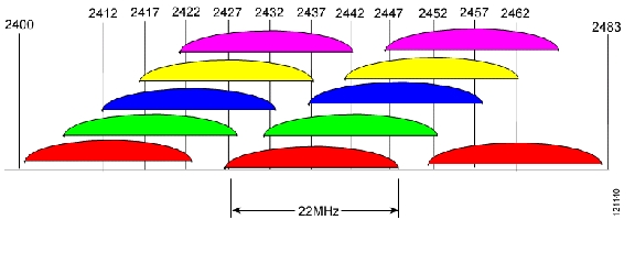
The level of RF energy that crosses between these channels determines interference. Radios do not have an exact edge to their channel, and energy spreads beyond the edges of the channel boundaries. However, the overall energy level drops as the signal spreads farther from the center of the channel. The 802.11b standard defines the required limits for the energy outside the channel boundaries (+/- 11 MHz), also known as the spectral mask.
Figure 2 shows the 802.11b spectral mask, which defines the maximum permitted energy in the frequencies surrounding the channel's center frequency (or fc).
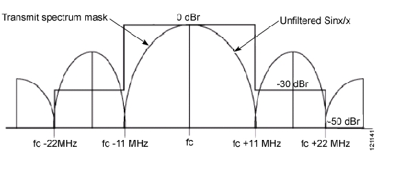
The energy radiated by the transmitter extends well beyond the 22-MHz bandwidth of the channel (+/- 11 MHz from fc). At 11 MHz from the center of the channel, the energy must be 30 dB lower than the maximum signal level, and at 22 MHz away, the energy must be 50 dB below the maximum level. As you move farther from the center of the channel, the energy continues to decrease but is still present, providing some interference on several more channels.
The worst-case scenario is a 100-mW transmitter and a good receiver. E.g., a Cisco Aironet 350 radio transmits at 100 mW, or +20 dBm. The 350 receiver can receive signals as low as -85 dBm (and even down to -93 dBm at 1 Mb).
Therefore, at 11 MHz away, the energy from the transmitter is 35 dB below the maximum (100 mW/20 dBm), putting it at a possible -15 dBm. Move another 11 MHz away, and the signal level is 50 dB below the maximum (100 mW/20 dBm or -30 dBm), which is still over 50 dB higher than the receiver needs to receive properly. In short, the receiver still hears the signal, even at 22 MHz away.
In a multiple cell network topology, overlapping and/or
adjacent cells using different channels can operate simultaneously without
interference if the distance between the center frequencies is at least 25 MHz.
FCC channels are as follows:
CHNL_ID Frequency
1 2412
2 2417
3 2422
4 2427
5 2432
6 2437
7 2442
8 2447
9 2452
10 2457
11 2462
12 2467
— > Not allowed
13 2472
— > Not allowed
14 2484
— > Not allowed
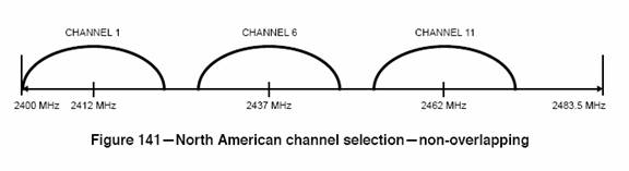
Example: You can use 1, 6 and 11 at the same time.
Alternate-Channel
Rejection: The adjacent channel rejection shall be equal to or better
than 35 dB.
Test: Signal level is at -70dBm
Adjacent Channel Blocker is at -35dBm.
2-Minimum Signal Level:
Minimum Signal Level = -76 dBm (to decode 11Mbps data) according to IEEE 18.4.8.1
= -85 dBm according to some industrial products
Minimum SNR= 10dB/16dB (depends on the baseband architecture which will decode 11 Mbps the data for a certain BER/PER)
Minimum SNR*=10dB for 11Mbps, 8dB for 5.5Mbps, 6dB for 2Mbps, 4dB for 1Mbps (IEEE 19.5.1 for a 8% BER)
=16dB for 11Mbps, 11dB for 5.5Mbps, 7dB for 2Mbps, 4dB for 1Mbps (Industry products for a 10% BER)
For this project: It is sufficient to get IEEE specs for 11Mbps reception.
Link Budget Analysis for 802.11b receiver:
Sensitivity Level=Noise Floor + Channel Bandwidth + min SNR for demodulation + Noise Figure of the receiver path
-76 dBm = 10.log10(K.T) + 10.log10(22 MHz) + 10 dB + NF
As an exercise, find the NF of the
receiver path for your design. Check Razavi, RF Microelectronics, Chapter 2,
for the definition of Noise Figure.
3-Maximum Signal Level:
Maximum Signal Level = -10dBm
The following discussion is for channel 1. Same SNR value should be satisfied. For example, if you choose min SNR as 10 dB, the IM3 products should be 10dB lower than your in band signal. There are two tests you should do to check this spec. (All numbers are given for 10 dB of minimum SNR)
1) In band IM3 : Two -10 dBm in band sinusoid signals (i.e 2410 MHz and 2414 MHz) should not create IM3 products higher than -20 dBm.
Note: This test will be sufficient to
satisfy the min. SNR in the presence of the maximum signal, even though the
test doesn’t represent a realistic case. As a reminder, the real spectrum of
the signal has a sin(x)/x like shape, not a single tone, after some filtering
that we have mentioned before in Fig. 2.
2) Out-of-band IM3: When the desired signal level is -70 dBm, two -35 dBm adjacent channel blockers (i.e 2437 MHz and 2467 MHz sinusoid signals) should not create input referred IM3 products higher than -80 dBm.
Note: All the signal levels that are mentioned above are the signal levels at the antenna, not at the input of your LNA.
Note: The specifications are derived from
the IEEE standards and some datasheets. Please check the links to see how to
derive the system design specifications from standards.
Note: All the specifications in this page
are related to the whole system, not individual blocks. We will give the
specifications of each individual block in the assignments. At the final stage
of the design, you have to check whether your design satisfies the overall
system specifications given above.
LINKS:
§ There are 3 pdf files. Please also check FCC rules that have been referred to in the files
§ http://en.wikipedia.org/wiki/802.11b
§ http://www.maxim-ic.com/view_press_release.cfm/release_id/686/ln/en
§ http://www.dlink.com/products/resource.asp?pid=9&rid=21
§ Sample publication for low-IF 2.4 GHz WLAN receiver
§
We will design a zero-IF receiver. So, do some
research to find related publications.